
System for treating VOCs

A pipeline and shell technology, applied in the field of VOCs management system, can solve the problems of increased total energy consumption of safe enterprises, hidden dangers of explosion in air passages, and failure to fully consider the actual production situation, and achieve excellent energy saving and stable emission reduction effect. , the effect of reducing energy consumption

Inactive Publication Date: 2018-10-12
佛山市佳威节能环保设备有限公司
View PDF13 Cites 1 Cited by
  • Summary
  • Abstract
  • Description
  • Claims
  • Application Information

AI Technical Summary

Problems solved by technology

However, these technologies reported or used are mainly considered from the point of view, that is, only committed to the reduction of total VOCs emissions to the atmosphere (that is, emission reduction), which often brings other new problems, such as secondary pollution, use safety and the increase in the total energy consumption of enterprises, etc., few technologies proceed from the actual production situation of the industry that produces VOCs, systematically carry out VOCs governance, and solve the problems of energy saving, emission reduction and safety at one time
However, the clean air flow does not pass through the atmosphere, but forms an air circulation. When a small amount of fresh air continues to enter the production equipment, the pressure will gradually increase, and the entire air flow channel has a safety hazard of explosion; and this technology only mentions the VOCs air circulation. Part, did not fully consider the actual production, there is still a certain distance from the system processing technology

Method used


Image

  • System for treating VOCs

Examples


Embodiment Construction

[0025] Embodiments of the present invention are described in detail below, examples of which are shown in the drawings, wherein the same or similar reference numerals designate the same or similar elements or elements having the same or similar functions throughout. The embodiments described below by referring to the figures are exemplary only for explaining the present invention and should not be construed as limiting the present invention.

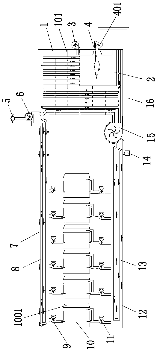
[0026] Refer below figure 1 Describe a VOCs treatment system according to an embodiment of the present invention, including a housing 1 and a partition 101, the partition 101 separates the housing 1 into a slow-flow air channel, and a high-temperature furnace 2 for heating the slow-flow air channel is installed in the slow-flow air channel Wherein the housing 1 is respectively provided with a return air heating device and a preheating device, at least one oven 10 is arranged between the return air heating device and the preheating device...


PUM


Abstract

The invention relates to a system for treating VOCs. The system comprises a shell body and a partition plate, the partition plate divides a high-temperature furnace into a slow-flow air channel, and the high-temperature furnace used for heating the slow-flow air channel is arranged in the slow-flow air channel; the shell body is provided with an returning air heating device and a preheating devicecorrespondingly, and at least one drying oven is arranged between the returning air heating device and the preheating device; one sides of the drying ovens are connected with the returning air heating device through hot air blowers, and the other sides of the drying ovens are connected with the preheating device through exhaust gas extracting fans; and a spraying pipe is arranged in the high-temperature furnace, the spraying pipe is connected with a fresh air blower, and one end of the fresh air blower is connected with the preheating device. The system has the beneficial effect of being morestable and more thorough in emission reduction, wherein the air flow with VOCs passes through the slow-flow air channel, the returning air heating device and the preheating device in a circulating mode, the VOCs air flow has no direct emission of the VOCs to the atmosphere, only a small amount of the VOCs enter the return air heating device or the preheating device when pressure relief is needed,and under the situation that sufficient natural gas flame burning and heat is achieved, the small amount of the VOCs is thoroughly treated.

Description

technical field [0001] The invention relates to a system for controlling VOCs. Background technique [0002] The pollution of VOCs in my country has been widely concerned from the government to the public, and its treatment is imminent. So far, VOCs treatment technology can be divided into source reduction technology, process control technology and terminal treatment technology. Judging from the existing domestic VOCs control situation, various industries mainly adopt terminal treatment technology to take control measures for volatile organic compounds that have been produced. Among them, adsorption, absorption, condensation, and combustion technologies are relatively mature and widely used in the traditional field of organic waste gas treatment; membrane separation, biotechnology, and plasma technology are emerging technologies that have also received widespread attention in the near future. However, these technologies reported or used are mainly considered from the poin...

Claims


Application Information

Patent Timeline
Patent Type & Authority Applications(China)
IPC IPC(8): F23G7/07
CPCF23G7/07
Inventor 郭满强
Owner 佛山市佳威节能环保设备有限公司
Learn More