
Patsnap Eureka
For R&D, Patsnap Eureka makes reading and utilizing patents & technical documents easy.
Patsnap Eureka AIR
Designed for self-driven R&D workflows. Generate viable solutions, solve complex R&D challenges, empower your innovation with AI.

Patsnap Eureka Materials
Designed for material experts only. Revolutionize your material R&D, from search, analyze, to developing new materials.

TechResearch
Generate reliable direction feasibility study reports for your R&D in just a few steps.

TechSeek
Discover and master advanced knowledge NOW. Basics, ideas, possibilities, all at once.

TechMind
As an expert in R&D Theories, TechMind can generates customized viable solutions instantly.

TechRisk
Analyze your overall solution with one click, know your potential R&D risks in advance.

TechMonitor
Get weekly tech updates, stay abreast of the latest tech innovations and key insights.
Electric furnace smoke dual-working medium heat exchange compound cycle superheated steam system
A technology of circulating superheat and steam system, applied in the field of flue gas waste heat recovery, can solve the problem of low recovery effect of electric furnace flue gas waste heat, and achieve the effect of extensive utilization value, reducing energy consumption per ton of steel and improving economic benefits.
- Summary
- Abstract
- Description
- Claims
- Application Information
AI Technical Summary
Problems solved by technology
Method used
Image

Examples
Embodiment 1
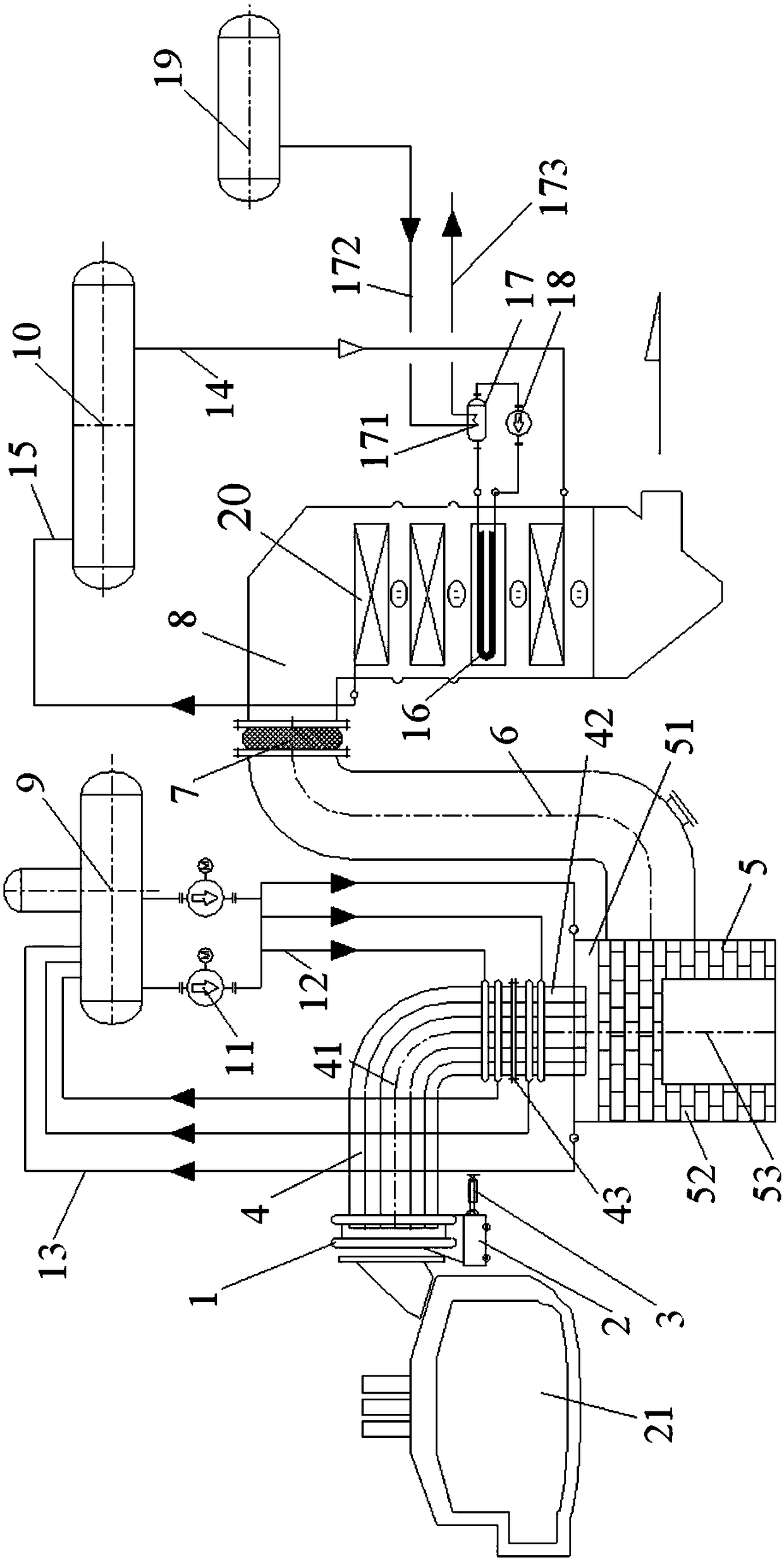
[0026] An electric furnace flue gas duplex heat exchange composite cycle superheated steam system, comprising a first flue 4, a combustion settling chamber 5, a second flue 6 and a waste heat boiler 8 connected in sequence, the electric furnace flue gas duplex The thermal compound cycle superheated steam system also includes a steam drum 10, a storage tank 17, a heat exchanger 171 and a heat accumulator 19. The waste heat boiler 8 is equipped with a steam-water heat exchanger 20 and a heat storage heat exchanger 16. The first steam drum 10 An outlet is connected with the inlet of the steam-water heat exchanger 20 through the first steam-water circulation descending pipeline 14, and the first inlet of the steam drum 10 is connected with the outlet of the steam-water heat exchanger 20 through the first steam-water circulation ascending pipeline 15, and the storage tank 17 The outlet of the storage tank 17 is connected with the inlet of the heat storage heat exchanger 16 through t...
Embodiment 2
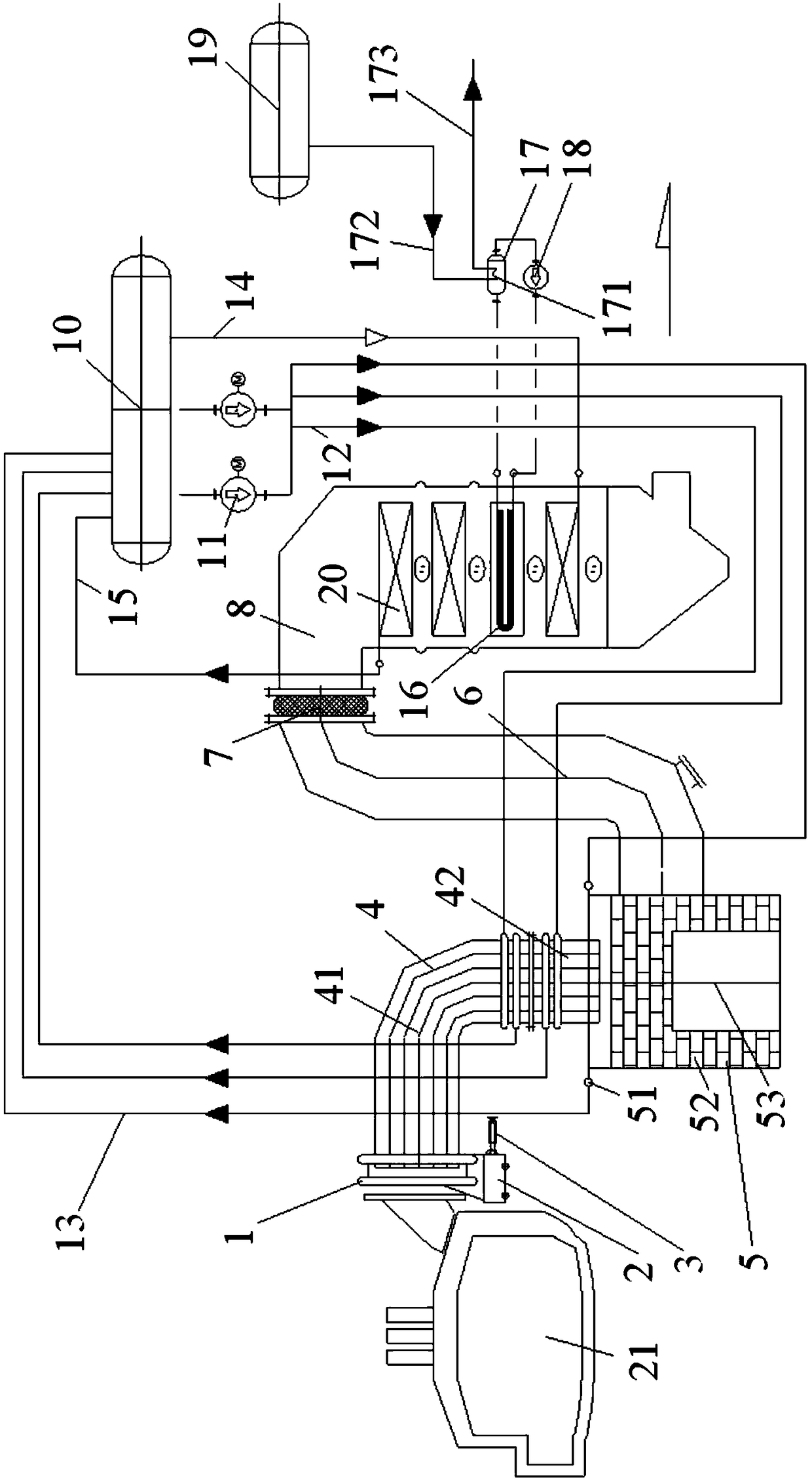
[0044] This embodiment is an improvement to Embodiment 1. In Embodiment 1, a deaerator 9 is used to carry out a low-pressure cycle. In this embodiment, the electric furnace flue gas duplex heat exchange compound circulation superheated steam system adopts a high-pressure circulation system, such as figure 2 As shown, at this time, the electric furnace flue gas duplex heat exchange compound cycle superheated steam system does not contain the deaerator 9 , and the main difference between this embodiment and the embodiment 1 is the absence of the deaerator 9 .
[0045] In addition, in this embodiment, the second outlet of the steam drum 10 is respectively connected to the inlet of the first water-cooling structure, the inlet of the second water-cooling structure and the inlet of the third water-cooling structure through the second steam-water circulation downpipe 12 The second inlet of the steam drum 10 is respectively connected to the outlet of the first water-cooling structure...
PUM
 Abstract
Description
Claims
Application Information
 - R&D Engineer
- R&D Manager
- IP Professional
- Industry Leading Data Capabilities
- Powerful AI technology
- Patent DNA Extraction
Browse by: Latest US Patents, China's latest patents, Technical Efficacy Thesaurus, Application Domain, Technology Topic, Popular Technical Reports.
© 2024 PatSnap. All rights reserved.Legal|Privacy policy|Modern Slavery Act Transparency Statement|Sitemap|About US| Contact US: help@patsnap.com