Compact projection light source

A compact, light source technology, applied in the field of projection light sources, can solve the problems of unfavorable miniaturization, complex optical path, large occupied volume, etc., and achieve the effects of simple structure, small occupied volume and low production cost

Pending Publication Date: 2018-10-12
成都九天光学技术有限公司
View PDF0 Cites 7 Cited by
  • Summary
  • Abstract
  • Description
  • Claims
  • Application Information

AI Technical Summary

Problems solved by technology

[0004] The technical problem to be solved and the technical task proposed by the present invention are to improve the existing technology, provide a compact projection light source, and solve the problem that the traditional projection light source system in the current technology has a complicated optical path, takes up a large volume, and is not conducive to miniaturization.

Method used


Image

  • Compact projection light source
  • Compact projection light source
  • Compact projection light source

Examples


Embodiment 1

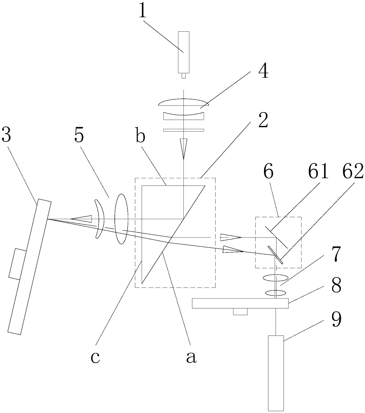
[0028] Such as figure 1 As mentioned above, the light source 1 is a blue laser light source, and the phosphor area on the fluorescent wheel 3 includes a green phosphor area, a red phosphor area and a reflection area;

[0029] A beam shaping part 4 is arranged between the light source 1 and the prism assembly 2. The light emitted by the light source 1 is compressed and shaped by the beam shaping part 4. The beam shaping part 4 can use a focusing lens and a diffuser, and the focusing lens can shape and compress the light spot and diffuse it. The chip is used to eliminate speckle, and at the same time make the spot distribution uniform, and improve the excitation efficiency of the phosphor on the phosphor wheel;

[0030] A focusing component 5 is set between the prism assembly 2 and the fluorescent wheel 3 to transmit and focus the reflected light coming from the prism assembly 2, to shape and transmit the radiated fluorescence excited on the fluorescent wheel 3, and to transmit ...

Embodiment 2

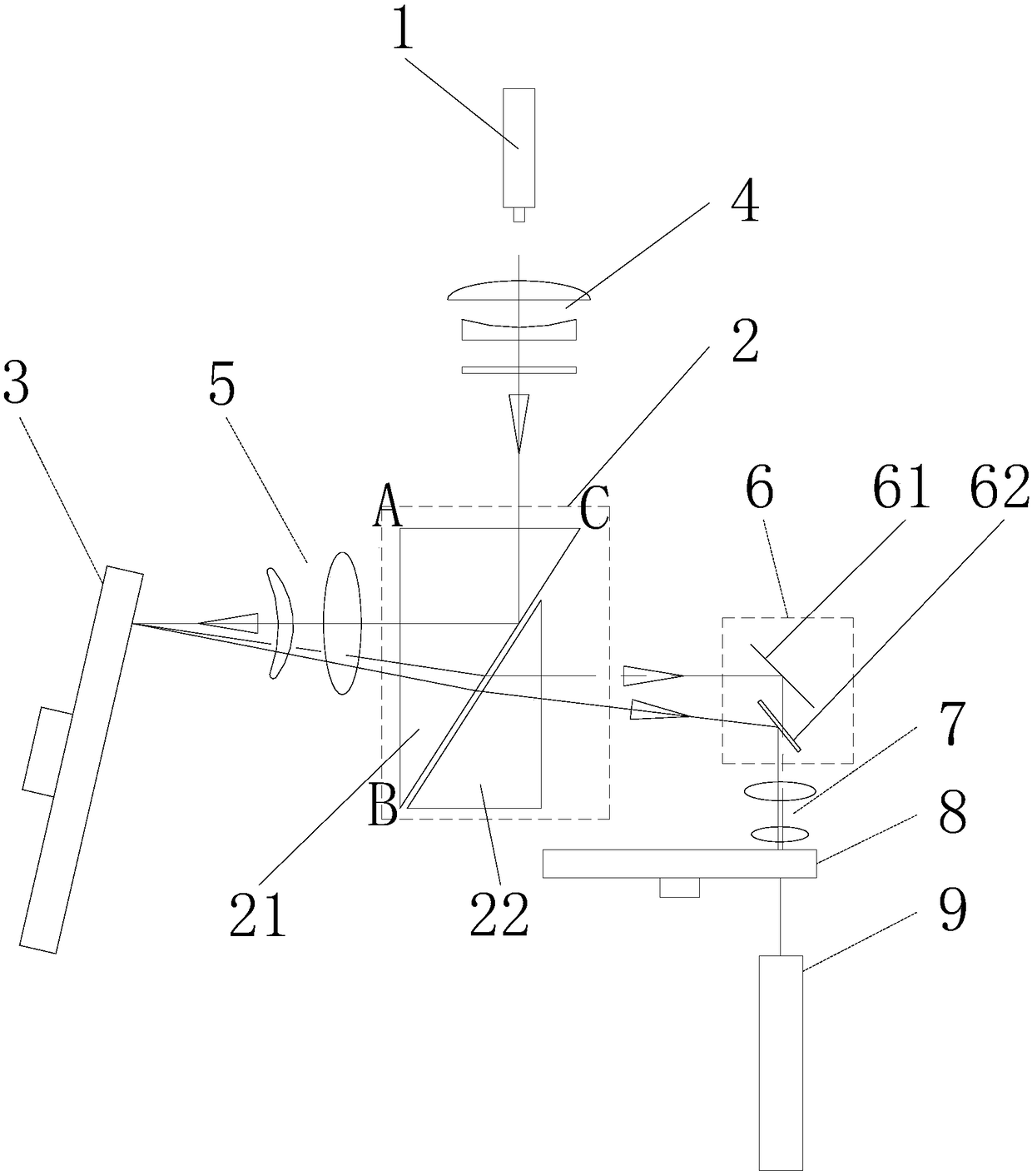
[0040] The difference from Embodiment 1 is that the prism assembly 2 adopts a TIR prism group, such as figure 2 As shown, in this embodiment, the TIR prism group is composed of two triangular prisms, including prism one 21 and prism two 22, prism one 21 has AB surface, AC surface and BC surface, BC surface is the first prism surface, light source The blue laser light emitted by 1 enters the prism-21 from the AC surface and exits from the AB surface to the fluorescent wheel 3 after total reflection on the BC surface, and the blue laser light and radiated fluorescence reflected from the fluorescent wheel enter the prism-21 from the AB surface It is incident on the BC surface at an angle smaller than the critical angle and then transmitted, and then the blue laser light and radiated fluorescence reflected from the fluorescent wheel are transmitted through the prism 22 and enter the light-combining component 6 to combine light and then output.

Embodiment 3

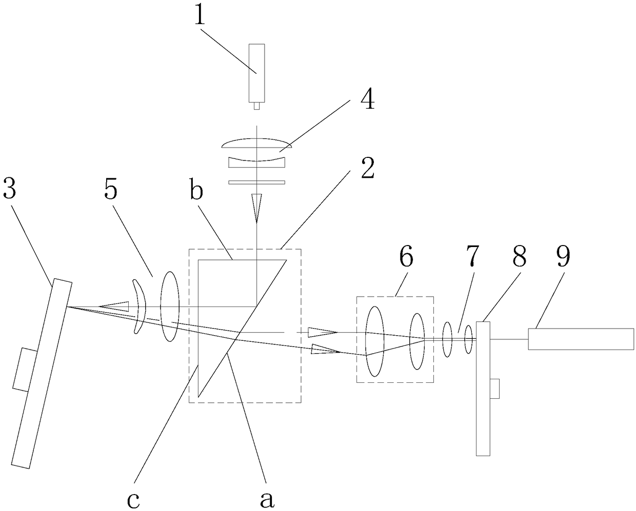
[0042] Such as image 3 As shown, the difference from Embodiment 1 is that the light-combining component 6 adopts a focusing lens group, and the blue laser light and radiated fluorescent light reflected from the fluorescent wheel are focused and transmitted by the focusing lens group and then enter the focusing element 7, and the optical path no longer needs refraction. Turn, making the optical path more compact and reducing the occupied volume.


PUM


Abstract

The invention discloses a compact projection light source. The light source comprises a light source body, a fluorescent wheel and a prism assembly arranged between the light source and the fluorescent wheel, the prism assembly is provided with a first prism surface, light emitted by the light source is emitted to the first prism surface in an angle greater than the critical angle, a first reflection light is obtained by the full reflection of the first prism surface, the first reflection light is emitted on the fluorescent wheel in the direction oblique to the rotary shaft of the fluorescentwheel, the fluorescent wheel is reflective fluorescent wheel, reflecting areas of a second reflection light obtained by conducting reflection on the first reflection light and a plurality of fluorescent powder areas used for generating irradiation fluorescence of different colors through excitation are distributed along the circumference of the fluorescent wheel, and the second reflection light and the irradiation fluorescence are combined and output by passing through a light combining component after the second reflection light and the irradiation fluorescence are emitted to the first prismsurface in an angle smaller than the critical angle. The light source has the advantages of being simple and compact in structure, less in optical path reflecting times, less in using components, lowin production cost, small in floor occupation area and good in using stability.

Description

technical field [0001] The invention relates to the technical field of projection light sources, in particular to a compact projection light source. Background technique [0002] Nowadays, more and more home appliance manufacturers are beginning to move closer to the laser TV product line. With the deepening of a series of brands, laser projection has gradually gained the attention of consumer groups. The light sources of projection systems are mainly divided into three categories, namely Bulb light source, LED light source and laser light source. Laser light source is the projection light source that has received the most attention in recent years. Laser light source has the characteristics of large wavelength selectivity and high spectral brightness. It can synthesize more than 90% of the color gamut coverage of natural colors seen by human eyes, and achieve perfect color reproduction. At the same time, the laser light source has ultra-high brightness and long service lif...

Claims


Application Information

Patent Timeline
Patent Type & Authority Applications(China)
IPC IPC(8): G03B21/20
CPCG03B21/204G03B21/2066G03B21/208
Inventor 黄宗荣彭水海张可根
Owner 成都九天光学技术有限公司
Why Eureka
Try Eureka