Solar cell module and preparation method thereof

A solar cell and module technology, applied in the field of solar cells, can solve problems such as lead-out of solder ribbons, inability to fully utilize the module area, and increase the risk of debris, so as to reduce the rate of debris, increase efficiency and installation costs, and enhance the ability to resist hot spots Effect

Active Publication Date: 2018-10-12
JA SOLAR
View PDF10 Cites 7 Cited by
  • Summary
  • Abstract
  • Description
  • Claims
  • Application Information

AI Technical Summary

Problems solved by technology

[0006] Therefore, in the production of vertical shingled modules in the prior art, if it is necessary to incorporate diodes, the battery strings need to be segmented, and then the battery strings are connected using busbars, so the area of ​​the modules cannot be fully

Method used


Image

  • Solar cell module and preparation method thereof
  • Solar cell module and preparation method thereof
  • Solar cell module and preparation method thereof

Examples


Example Embodiment

[0074] Example 1

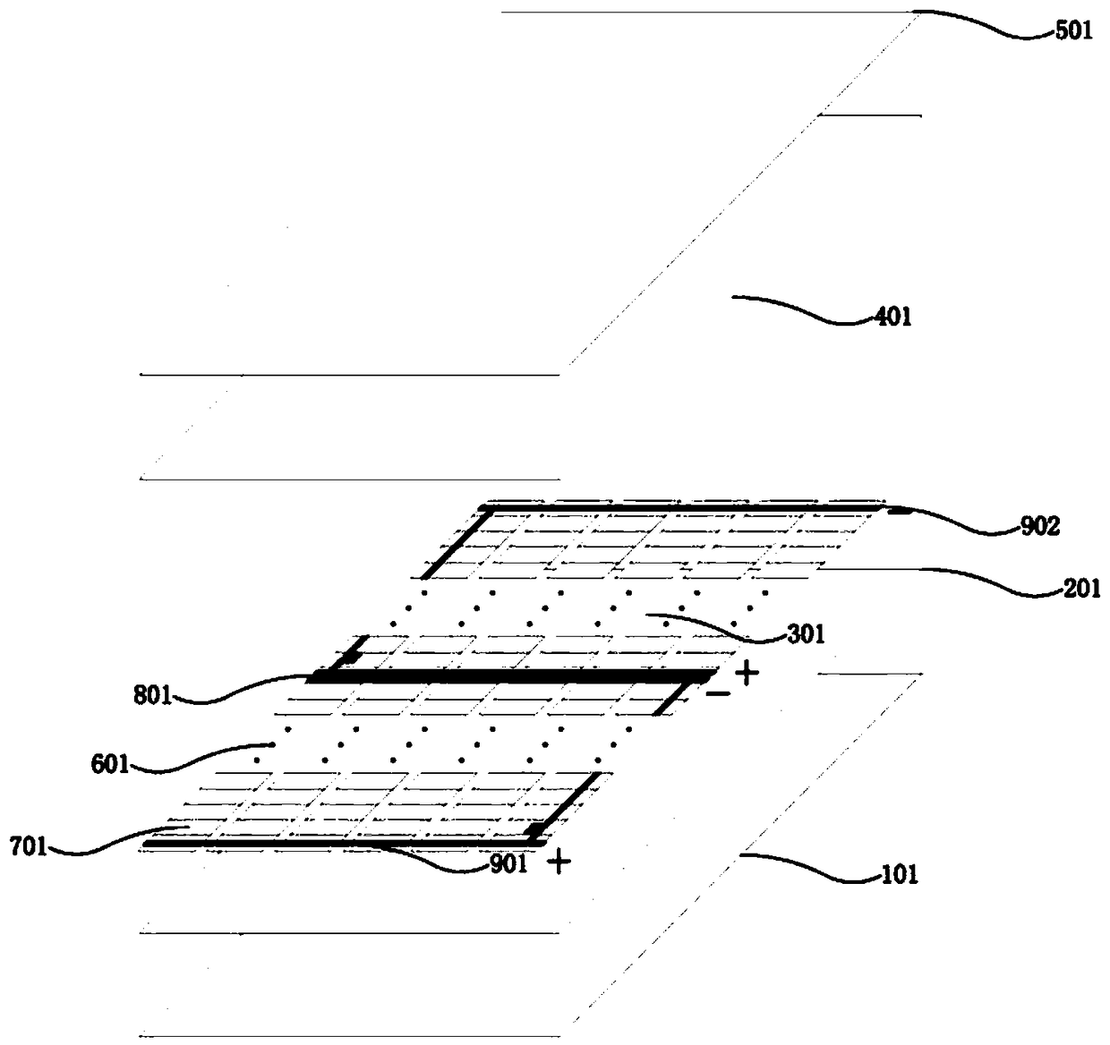
[0075] figure 1 It is a schematic structural view of the solar cell module in Embodiment 1 of the present invention, as figure 1 As shown, the shingled solar cell module provided in this embodiment includes a cover material 101, a first encapsulant film 201, battery strings 301, a second encapsulant film 401, and a back sheet material 501 in sequence from bottom to top. , the battery string group 301 is formed by connecting multiple battery strings 601, and each battery string 601 is formed by connecting multiple first-type battery slices 701 and at least one second-type battery slice 801, wherein multiple first-type battery slices The polarities of the front electrodes of 701 are consistent, and the polarities of the back electrodes of the plurality of first-type battery sheets 701 are also consistent, and the front electrodes of the plurality of first-type battery sheets 701 and the polarities of the plurality of first-type battery sheets 701 The polarit...

Example Embodiment

[0107] Example 2

[0108] The structure of the solar cell module provided in this embodiment is the same as that in Embodiment 1.

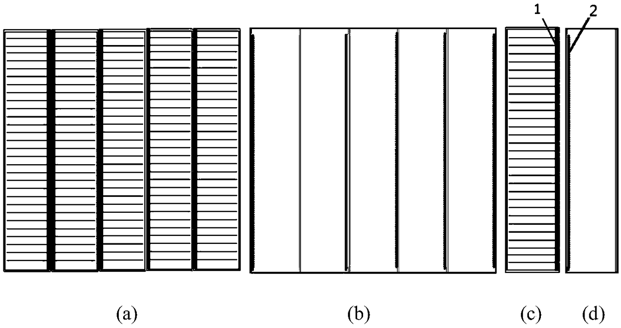
[0109] The first battery sheet is a conventional battery sheet, and the conventional battery is the same as in Example 1, such as figure 2 and image 3 As shown, the front and back sides of the first type of solar cell are respectively provided with main grids, and the whole solar cell before cutting is cut at the reserved position close to the main grid to form multiple first type of solar cells, and the main grids are distributed in On the long side of the first type of battery and perpendicular to the short side of the first type of battery.

[0110] like Figure 8 As shown, the second type of battery sheet is a back contact battery sheet, the front side of the back contact battery sheet is not provided with electrodes, and the positive and negative electrodes of the back contact battery sheet are all arranged on the back side of the back ...

Example Embodiment

[0122] Example 3

[0123] The structure of the solar cell module provided in this embodiment is the same as that in Embodiment 1.

[0124] like figure 2 As shown, the front and back of the first battery sheet are respectively provided with busbars, and the first battery sheet is cut near the reserved position of the busbar to form a plurality of first battery sheets, and the busbars are distributed on the first battery sheet. On the long side of the cell and perpendicular to the short side of the first type of cell.

[0125] like Figure 10 As shown, the second type of cell is a back-contact cell. There is no electrode on the front of the back-contact cell, and the positive and negative electrodes of the back-contact cell are both arranged on the back of the back-contact cell. Cutting is performed near the reserved position of the main grid on the back to form a plurality of second battery slices b". The distribution of main grids with the same characteristics, all the ma...


PUM


Abstract

The invention discloses a solar cell module. The solar cell module comprises a cover plate material, a first encapsulation adhesive film, a cell string group, a second encapsulation adhesive film anda back plate material; and the cell string group is formed by connecting multiple cell strings, and each cell string is formed by connecting multiple first cells with at least one second cell, whereinthe back faces of at least one of the multiple first cells are provided with first current export units, and the back faces of the at least one second cell are provided with second current export units. According to the solar cell module, the cells with two different structures are adopted for imbricated connection, the current export units can be lead out from the back faces of the cells, the difficulty of merging diodes is lowered, and the area of the module is not increased; and the fragmentation rate of the solar cells can be decreased, therefore, the module yield is increased, and the module efficiency is improved. The invention further discloses a preparation method of the solar cell module.

Description

technical field [0001] The invention belongs to the technical field of solar cells, in particular to a solar cell component and a preparation method thereof. Background technique [0002] With the continuous development of society, human beings pay more and more attention to the use of renewable energy, and solar energy is the easiest energy for us human beings to obtain. How to use solar energy has always been a research topic for human beings. Among them, solar photovoltaic cells convert solar energy into electrical energy one of the most effective ways. In recent years, the world output of solar cells has grown at an annual rate of 30-40%, becoming one of the fastest growing industries in the market, among which crystalline silicon solar cells are becoming more mature and occupying a leading position in the market. [0003] With the development of crystalline silicon solar cell technology, various high-efficiency cell technologies have gradually matured. Compared with co...

Claims


Application Information

Patent Timeline
IPC IPC(8): H01L31/05H01L31/048
CPCH01L31/048H01L31/0504Y02E10/50H01L31/044H02S20/25H02S40/34H01L31/042Y02B10/10H01L31/049H02S50/15H01L31/0516
Inventor 陈宏月周艳方
Owner JA SOLAR
Why Eureka
Try Eureka