Continuous type welding-free lead storage battery pole plate and manufacturing method thereof
The technology of a lead-acid battery and its manufacturing method is applied in the direction of lead-acid battery electrodes, lead-acid batteries, lead-acid battery construction, etc., which can solve problems such as missing welding, battery plates falling off, and not being firm, so as to eliminate the welding process, The effect of reducing lead consumption and improving product quality and reliability
- Summary
- Abstract
- Description
- Claims
- Application Information
AI Technical Summary
Problems solved by technology
Method used
Image

Examples
Embodiment 1
[0063] First, lead alloy plates with a certain length, width and thickness are prepared by using lead plate production equipment.
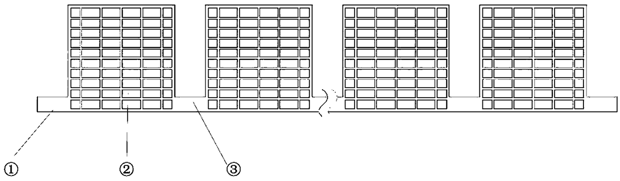
[0064] Secondly, according to the battery size and capacity requirements, refer to Figure 1-Figure 6 As shown, the lead plate is processed into a continuous lead battery grid by using lead plate punching equipment. The number of coated areas of the grid is 6, located in the middle of the grid, and its structural shape is a vertical grid; the number of connecting areas is 5, located between the coated areas; the number of terminal areas is 1, located at one end of the grid.
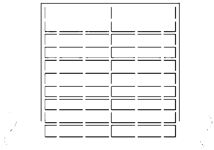
[0065] Third, according to the battery capacity requirements, refer to Figure 7 As shown, the positive electrode active material is coated on the plate coating area, and then through the steps of plate curing, connection area cleaning, etc., a continuous type welding-free lead battery positive plate suitable for lead-acid batteries is obtained.
[0066] Fourth, according t...
Embodiment 2
[0068] First, according to the battery size and capacity requirements, refer to Figure 1-Figure 6 As shown, a continuous type lead battery grid mold was prepared.
[0069] Secondly, the molten lead liquid is injected into the mold by casting process to produce continuous lead battery grid. The number of coated areas of the grid is 2, located in the middle of the grid, and its structural shape is a radial grid; the number of connecting areas is 1, located between the coated areas; the number of terminal areas is 2, located at both ends of the grid.
[0070] Third, according to the battery capacity requirements, refer to Figure 7 As shown, the negative electrode active material is coated in the coating area, and then through the steps of plate curing and connection area cleaning, a continuous welding-free lead battery negative plate suitable for lead-acid batteries is obtained.
[0071] Fourth, according to the design requirements of the battery, refer to Figure 8 , after ...
Embodiment 3
[0073] First, lead alloy plates with a certain length, width and thickness are prepared by using lead plate production equipment.
[0074] Secondly, according to the battery size and capacity requirements, refer to Figure 1-Figure 6 As shown, the lead plate is processed into a continuous lead battery grid by using lead plate punching equipment. The number of coating areas of the grid is 11, of which 6 consecutive blocks on one side are negative electrode active material coating areas, and 5 continuous blocks on the other side are positive electrode active material coating areas, and the coating area is located in the middle of the grid. Its structural shape is flat; the number of connection areas is 10, located between the coated areas; the number of terminal areas is 1, located at one end of the grid.
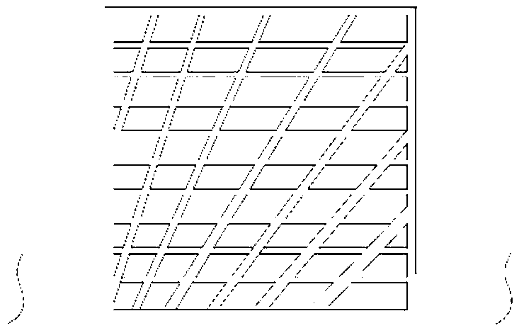
[0075] Third, according to the battery capacity requirements, refer to Figure 9 As shown, the positive electrode active material is coated on both sides of the lead plate ...
PUM
 Abstract
Description
Claims
Application Information
 - R&D
- Intellectual Property
- Life Sciences
- Materials
- Tech Scout
- Unparalleled Data Quality
- Higher Quality Content
- 60% Fewer Hallucinations
Browse by: Latest US Patents, China's latest patents, Technical Efficacy Thesaurus, Application Domain, Technology Topic, Popular Technical Reports.
© 2025 PatSnap. All rights reserved.Legal|Privacy policy|Modern Slavery Act Transparency Statement|Sitemap|About US| Contact US: help@patsnap.com