
Laser

A laser and grating technology, applied in the field of lasers, can solve the problems of high production cost, large band-pass filter size, complex CML chip structure, etc., and achieve the effect of reducing production cost, improving overall stability, and simple assembly process

Inactive Publication Date: 2018-10-12
HISENSE BROADBAND MULTIMEDIA TECH
View PDF5 Cites 12 Cited by
  • Summary
  • Abstract
  • Description
  • Claims
  • Application Information

AI Technical Summary

Problems solved by technology

But this CML still has some deficiencies, which are, 1. The size of the bandpass filter in the device is relatively large; 2. The device includes a complex optical system, and has high requirements for the stability of each optical component; resulting in The structure of the CML chip is very complicated, and its production cost is relatively high

Method used


Image

  • Laser
  • Laser
  • Laser

Examples


Embodiment Construction

[0016] In order to make the object, technical solution and advantages of the present invention more clear, the present invention will be further described in detail below in conjunction with the accompanying drawings and embodiments. It should be understood that the specific embodiments described here are only used to explain the present invention, not to limit the present invention.

[0017] In describing the present invention, it should be understood that the terms "center", "longitudinal", "transverse", "length", "width", "thickness", "upper", "lower", "front", " Orientation indicated by rear, left, right, vertical, horizontal, top, bottom, inside, outside, clockwise, counterclockwise, etc. The positional relationship is based on the orientation or positional relationship shown in the drawings, which is only for the convenience of describing the present invention and simplifying the description, rather than indicating or implying that the referred device or element must hav...


PUM


Abstract

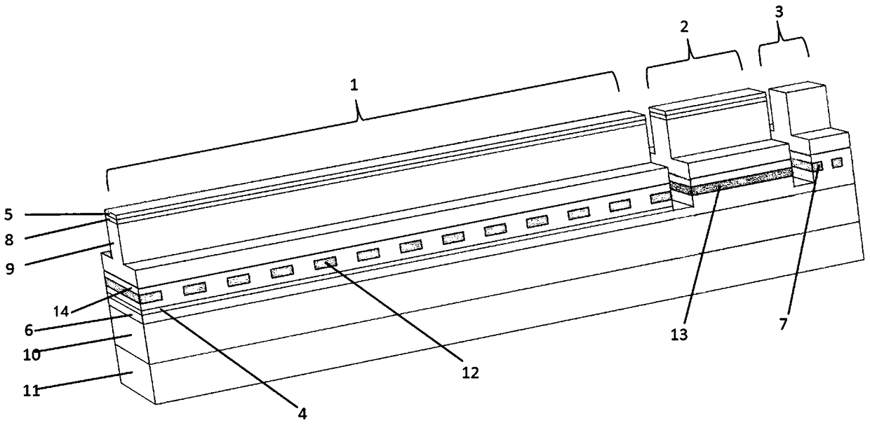
The invention relates to the technical field of optical fiber communication, specifically relates to a laser. The laser comprises an N type electrode, a substrate, a lower limiting layer and a lower waveguide layer which are arranged from the bottom up in sequence; a first active waveguide region, a second passive filtering waveguide region and a third passive coupled waveguide region which are separated mutually are arranged above the lower waveguide layer; a quantum well layer is arranged in the first active waveguide region; a one-order grating is arranged on the quantum well layer; a P type electrode is arranged on the top of the first active waveguide region; a grating material layer is arranged in the second passive filtering waveguide region; a P type electrode is arranged on the top of the second passive filtering waveguide region; a two-order grating is arranged in the third passive coupled waveguide region; and a light beam generated by exciting the quantum well layer passesthrough the one-order grating, the grating material layer and the two-order grating in sequence to be output from the top of the third passive coupled waveguide region. The laser is very simple in assembling process, the manufacturing cost of a device is lowered effectively, the overall stability of the device is improved, and the packaged dimension is reduced.

Description

technical field [0001] The invention relates to the technical field of optical fiber communication, in particular to a laser. Background technique [0002] With the continuous development of optical fiber communication network, the communication bandwidth it needs is also increasing, and now high-speed optical modules have become the mainstream trend of market development. The most critical device in the high-speed optical module is the DFB (Distributed Feed Back) chip. According to different modulation methods, the chips can be divided into two categories, one is external modulation chips, including electro-absorption modulated lasers (EML) and Mach-Zehnder modulator type distributed feedback lasers (MZ-DFB); the other is The class is a direct modulation type DFB chip. The frequency chirp generated by the externally modulated transmitter chip under high-speed modulation is small, and the signal broadening caused by the dispersion of single-mode fiber during transmission i...

Claims


Application Information

Patent Timeline
Patent Type & Authority Applications(China)
IPC IPC(8): H01S5/12H01S5/20H01S5/34
CPCH01S5/12H01S5/20H01S5/34
Inventor 魏思航洪志苍王忠政方瑞禹
Owner HISENSE BROADBAND MULTIMEDIA TECH
Learn More