
Flat shunting mechanical control device with high-accurate positioning

A machine controller, high-precision technology, applied to signal indicators on vehicles, railway car body parts, and transportation center control systems, etc., can solve problems such as low channel utilization, slow data processing speed, and transmission failure. Achieve the effects of improving voice clarity, fast data transmission speed, and improving anti-interference ability

Pending Publication Date: 2018-10-16
泉州市铁通电子设备有限公司
View PDF5 Cites 2 Cited by
  • Summary
  • Abstract
  • Description
  • Claims
  • Application Information

AI Technical Summary

Problems solved by technology

[0003] With the increasing speed of existing railway lines and the large-scale construction of high-speed railways, the business volume of railways is increasing, and the performance requirements for railway cluster communication equipment are getting higher and higher. The existing railway wireless shunting light display information management system adopts Analog equipment has defects such as weak anti-interference ability, slow data processing speed, and low channel utilization rate, which lead to low communication efficiency of shunting operations such as shunting operation notices and shunting instructions, delays in transmission of shunting instructions, transmission failure, etc. Unreliable transmission conditions cause confusion in the display of shunting signal indicators, etc., which affect the safety of shunting operations and cannot meet the needs of technological development and modern transportation production.

Method used


Image

  • Flat shunting mechanical control device with high-accurate positioning

Examples


Embodiment Construction

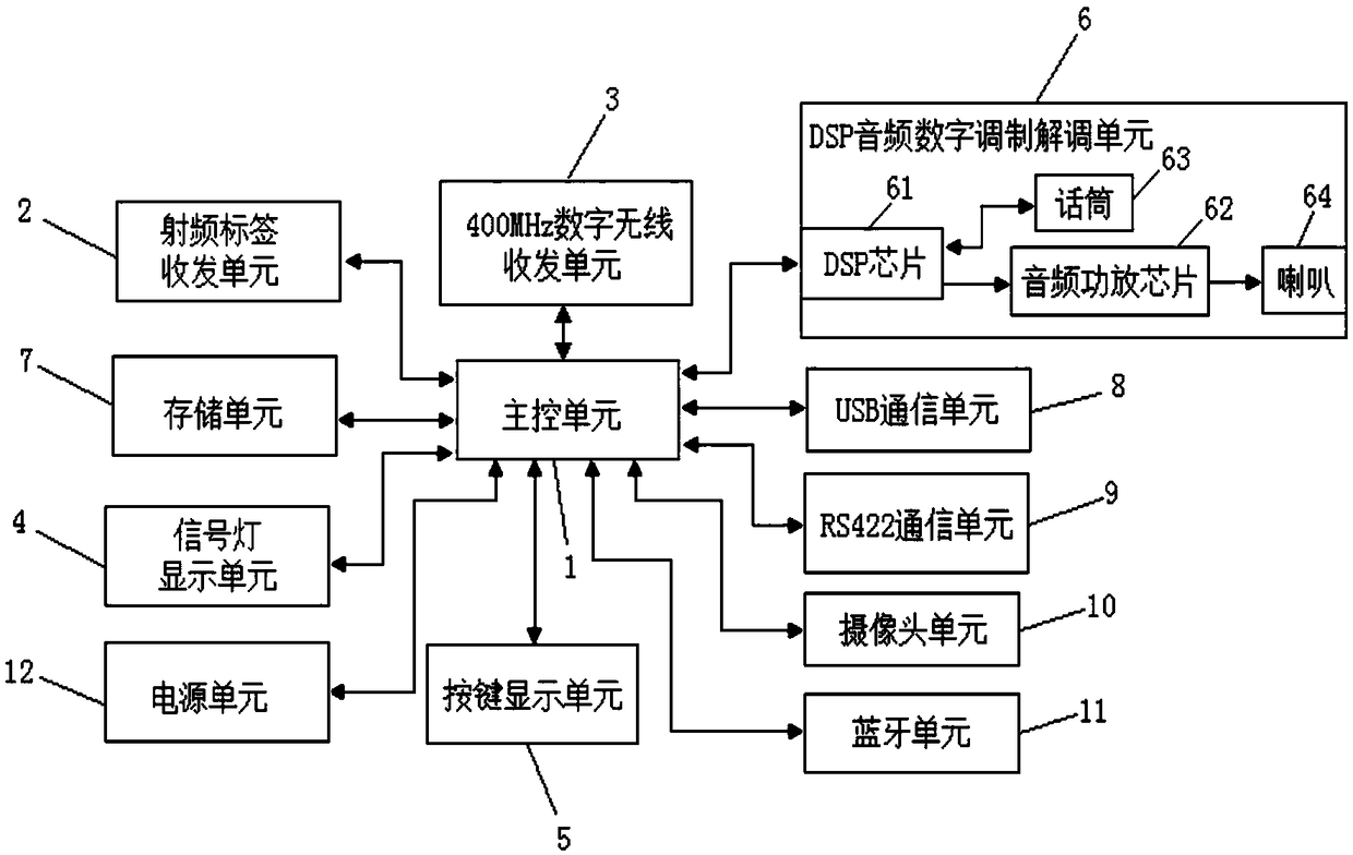
[0026] In order to further understand the structure, features and other purposes of the present invention, the attached preferred embodiments are now described in detail with accompanying drawings as follows. The embodiments described in the accompanying drawings are only used to illustrate the technical solutions of the present invention and are not limiting this invention.

[0027] like figure 1 as shown, figure 1It is a structural schematic diagram of the plane shunting machine controller of the present invention; the plane shunting machine controller supporting high-precision positioning includes a main control unit 1, a radio frequency tag transceiver unit 2, a 400MHz digital wireless transceiver unit 3, and a signal light display unit 4 , key display unit 5, DSP audio digital modulation and demodulation unit 6, storage unit 7, USB communication unit 8, RS422 communication unit 9, camera unit 10, bluetooth unit 11 and power supply unit 12. Main control unit 1 is connect...


PUM


Abstract

The invention discloses a flat shuntingmechanical control device with high-accurate positioning. According to the flat shunting mechanical control device, a main control unit is correspondingly electrically connected with a radio frequency tag receive-and-send unit, a 400MHz digital radio receive-and-sent unit, a signal lamp display unit, a button display unit, a DSP digital audio modulation-demodulation unit, a storage unit, a USB communication unit, a camera unit, a bluetooth unit and a power supply unit. The radio frequency tag receive-and-sent unit receives activation signals of an annuciator in a switchyard, and identifies field intensity of the activation signals; and the main control unit controls the radio frequency tag receive-and-sent unit to send positioning information to a base station at an ultrahigh frequency of 1.2G. A source radio frequency tag is adopted by the flat shunting mechanical control device, and through rapid identification of the base station to the sourceradio frequency tag in the covered range, accurate locating geographical location information of the mechanical control device is obtained by the base station and is sent to a dispatching center, so that the function of accurately locating a shunting locomotive by the dispatching center is achieved, and location error can be controlled within 0.3-1 meter.

Description

technical field [0001] The invention relates to a railway wireless shunting light display information management system, in particular to a planar shunting machine controller supporting high-precision positioning. Background technique [0002] The railway wireless shunting light display information management system equipment is mainly used in the plane shunting operations of railway stations and intermediate stations to realize the communication between the shunting crew, the locomotive driver, and the head of the shunting area, and to accurately transmit voice and shunting instructions , shunting operation notice and other information to ensure the smooth progress of shunting operations, improve the personal safety of operators, and effectively reduce the work intensity of operators. [0003] With the increasing speed of existing railway lines and the large-scale construction of high-speed railways, the business volume of railways is increasing, and the performance require...

Claims


Application Information

Patent Timeline
Patent Type & Authority Applications(China)
IPC IPC(8): B61L15/00B61L27/00B61L25/02
CPCB61L15/0018B61L15/0027B61L15/009B61L25/02B61L27/00Y02D30/70
Inventor 洪泉益洪杰辉林鸿友林救星
Owner 泉州市铁通电子设备有限公司
Learn More