
Centrifugal impeller vibration damping test system and method

A centrifugal impeller and vibration damping technology, which is applied in the field of compressors, can solve the problems that it is difficult to directly measure the vibration damping data of the rotating impeller, there is no impeller test system and method, and the aerodynamic damping is not simple and feasible, etc. Simple, simultaneous measurement, easy installation results

Active Publication Date: 2018-10-19
HEFEI GENERAL MACHINERY RES INST
View PDF5 Cites 2 Cited by
  • Summary
  • Abstract
  • Description
  • Claims
  • Application Information

AI Technical Summary

Problems solved by technology

[0003] It is difficult to directly measure the vibration damping data of the rotating impeller in actual operation. It can only be calculated from the vibration response data of the rotating impeller according to the structural dynamic equation.
Due to the high-speed rotation of the impeller, the primary problem to be solved is to transmit the vibration response signal of the impeller surface in the casing to the external terminal. In the existing technology, a conductive slip ring is often used to lead the data line on the surface of the rotating hub from the shaft end of the impeller. This technology Wired transmission is adopted, the wiring at the shaft end is complicated, and the structural reliability is low
At the same time, the impeller damping data obtained under the measured conditions is the total damping including material damping and aerodynamic damping. How to extract the aerodynamic damping from the measured damping data has not yet been found to be a simple and feasible method
In addition, the aerodynamic damping of the impeller changes due to different vibration modes and working conditions, so far no testing system and method for extracting the aerodynamic damping characteristics of the impeller has been proposed

Method used


Image

  • Centrifugal impeller vibration damping test system and method
  • Centrifugal impeller vibration damping test system and method
  • Centrifugal impeller vibration damping test system and method

Examples


Embodiment Construction

[0032] Below in conjunction with embodiment technical solution of the present invention is made more specific description:

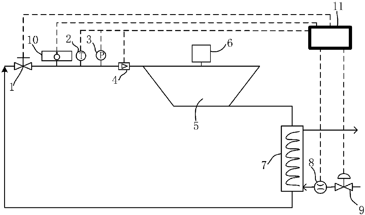
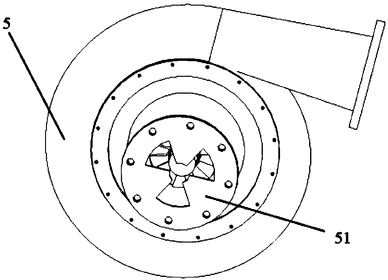
[0033] Such as figure 1 , 4 , 5: the centrifugal impeller vibration damping test system of the present invention includes a closed loop system, a wireless receiving gateway 10 and a terminal control unit 11:

[0034] The closed loop system includes a centrifugal compressor 5 to be tested and a cooler 7, a throttle valve 1, a temperature sensor 2, a pressure sensor 3, and a cooler 7 arranged sequentially from the outlet of the centrifugal compressor 5 to the inlet of the centrifugal compressor 5. A flow meter 4; the cold source inlet end of the cooler 7 is provided with a regulating valve 9 and a second flow meter 8 arranged in sequence along the flow direction of the cold source.

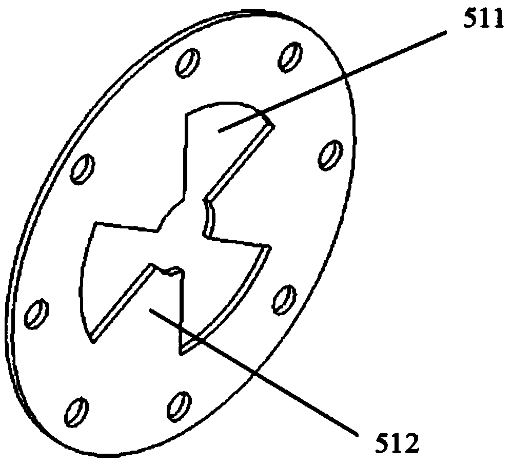
[0035] The surface of the centrifugal impeller 52 of the centrifugal compressor where it is located is equipped with a strain sensor 521 for measuring blade strain. The wir...


PUM


Abstract

The invention relates to a centrifugal impeller vibration damping test system and method. The test system includes a closed loop system in which a to-be-tested centrifugal compressor is located and awireless receiving gateway. The surface of a centrifugal impeller of the centrifugal compressor is provided with a strain sensor used for measuring the blade strain. The front shaft end of the centrifugal impeller is provided with a wireless emitter which is connected to the strain sensor through a data line and emits strain signals to the wireless receiving gateway. The wireless emitter synchronously rotates with the centrifugal impeller. The wireless emitter is connected to the shaft end of the centrifugal impeller and synchronously rotates with the centrifugal impeller. Therefore, the disadvantages of a conventional wired data transmission technologies that the wiring is complex and the reliability of the structure is low. The test system and method are beneficial to the improvement ofthe operational reliability and structural stability of the test system.

Description

technical field [0001] The invention belongs to the technical field of compressors, and in particular relates to a centrifugal impeller vibration damping test system and method. Background technique [0002] During the operation of modern industrial centrifugal compressors, the forced vibration induced by airflow excitation is an important factor leading to the fatigue damage of centrifugal impellers. In order to accurately predict the forced response characteristics of the centrifugal impeller, the complete mechanical parameters of the impeller components should be obtained, and the damping parameters are key data that are difficult to obtain, and the aerodynamic damping is the key to determining the aeroelastic stability. For the operation of advanced turbomachinery For health assessment issues, obtaining vibration damping data is the focus that must be paid attention to. The blades and discs of the centrifugal impeller are often processed in one piece, and the mechanical...

Claims


Application Information

Patent Timeline
IPC IPC(8): G01M7/02G01M13/00
CPCG01M7/025G01M13/00
Inventor 肖军于洋舒悦张谦谢传东
Owner HEFEI GENERAL MACHINERY RES INST
Features
  • Generate Ideas
  • Intellectual Property
  • Life Sciences
  • Materials
  • Tech Scout
  • Unparalleled Data Quality
  • Higher Quality Content
  • 60% Fewer Hallucinations
Learn More