
A lithium niobate electro-optic modulator

An electro-optic modulator, lithium niobate technology, applied in the direction of instruments, optics, nonlinear optics, etc., can solve the problem of high modulator half-wave voltage, to ensure high-speed modulation, increase electrode length, reduce DC half-wave voltage and The effect of microwave half-wave voltage

Active Publication Date: 2021-07-13
BEIJING AEROSPACE TIMES OPTICAL ELECTRONICS TECH
View PDF6 Cites 0 Cited by
  • Summary
  • Abstract
  • Description
  • Claims
  • Application Information

AI Technical Summary

Problems solved by technology

[0008] The above structure makes the half-wave voltage of the modulator larger

Method used


Image

  • A lithium niobate electro-optic modulator
  • A lithium niobate electro-optic modulator

Examples


Embodiment Construction

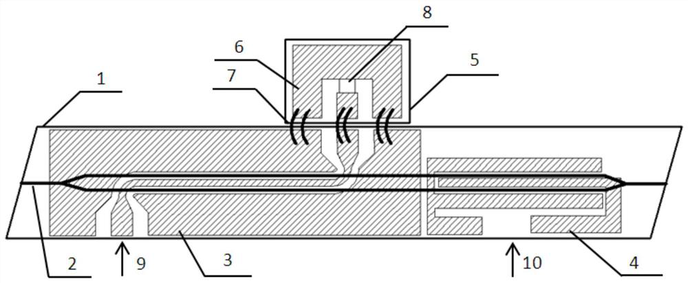
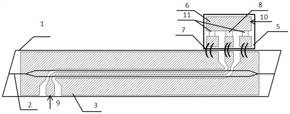
[0029] A low half-wave voltage lithium niobate electro-optic modulator, the modulator comprises a lithium niobate substrate 1, a waveguide 2, a traveling wave electrode 3 and a matching circuit 5;

[0030] The matching circuit 5 includes a matching electrode 6, a gold wire 7, a load resistor 8 and two capacitors 11;

[0031] The waveguide 2 is located inside the upper surface of the lithium niobate substrate 1;

[0032] The traveling wave electrode 3 is located on the upper surface of the lithium niobate substrate 1;

[0033] The waveguide 2 is located between the traveling wave electrodes 3;

[0034] The waveguide 2 is a Mach-Zehnder interference optical path, located inside the upper surface of the lithium niobate substrate 1;

[0035] The traveling wave electrode 3 is located on the upper surface of the lithium niobate substrate 1, is a coplanar waveguide structure, and is composed of three metal strips, the metal strip in the center is a signal electrode, and the metal s...


PUM

PropertyMeasurementUnit
lengthaaaaaaaaaa

Abstract

The invention relates to a lithium niobate electro-optic modulator, in particular to a low half-wave voltage lithium niobate electro-optic modulator, which belongs to the technical field of lithium niobate electro-optic modulators. The present invention combines the traveling wave electrode and the DC bias electrode into one, realizes the function of only loading the DC voltage on the center electrode of the traveling wave electrode through the capacitance on the matching circuit, and ensures the progress of the DC modulation. The high-frequency nature of the capacitor does not affect the propagation of microwaves, which ensures the high-speed modulation of the modulator. The integration of the device is improved. Under the condition of keeping the chip length and the overall size of the device unchanged, the electrode length on the chip is greatly increased, thereby greatly reducing the DC half-wave voltage and microwave half-wave voltage of the modulator.

Description

technical field [0001] The invention relates to a lithium niobate electro-optic modulator, in particular to a low half-wave voltage lithium niobate electro-optic modulator, which belongs to the technical field of lithium niobate electro-optic modulator. The half-wave voltage in the lithium niobate electro-optic modulator involved is lower than the half-wave voltage in the lithium niobate electro-optic modulator in the prior art. Background technique [0002] The research on integrated optical devices based on lithium niobate materials, such as integrated optical electro-optic modulators, optical switches, electric field sensors, and magnetic field sensors, has attracted the attention of many researchers. High-speed lithium niobate electro-optic modulators have the advantages of wide spectral operating range, low driving voltage, low insertion loss, high extinction ratio, zero or adjustable chirp, high reliability and easy mass production. Mainstream modulators in the fields...

Claims


Application Information

Patent Timeline
Patent Type & Authority Patents(China)
IPC IPC(8): G02F1/03G02F1/035
CPCG02F1/0316G02F1/0327G02F1/035
Inventor 周建伟夏君磊郑国康刘瑞丹乔建坤宁智超徐玉亮
Owner BEIJING AEROSPACE TIMES OPTICAL ELECTRONICS TECH
Learn More