Strain sensor based on optical fiber Fabry-Perot cavity and manufacturing method thereof

A strain sensor and Poirot cavity technology, which is applied in the direction of converting the sensor output, using optical devices to transmit sensing components, instruments, etc., can solve the problems of low mechanical strength of the sensor, difficult to control the cavity size, and low sensitivity, etc. The effect of strain measurement sensitivity, high production efficiency, and small size

Pending Publication Date: 2018-10-23
UNIV OF SCI & TECH OF CHINA
View PDF6 Cites 8 Cited by
  • Summary
  • Abstract
  • Description
  • Claims
  • Application Information

AI Technical Summary

Problems solved by technology

It is not easy to manufacture a cavity directly inside the optical fiber. Traditionally, the manufacturing methods of fiber optic bubble microcavities are chemical corrosion, laser processing, arc discharge, special optical fiber, or quartz tube. The fiber optic bubble cavity produced by these methods Most of the cavities are spheres, spheroids or cuboids, and the size of the cavity is difficult to control, and the sensitivity is not very high; through a series of processing procedures, complex cavity structures can also be made, so that the length of the interference cavity and the length of the effective cavity are not the same. etc., thereby improving the strain sensitivity, but the sensor obtained by this method will have the disadvantages of low mechanical strength, complicated process and large size

Method used


Image

  • Strain sensor based on optical fiber Fabry-Perot cavity and manufacturing method thereof
  • Strain sensor based on optical fiber Fabry-Perot cavity and manufacturing method thereof
  • Strain sensor based on optical fiber Fabry-Perot cavity and manufacturing method thereof

Examples


Embodiment Construction

[0027] In order to make the object, technical solution and advantages of the present invention clearer, the present invention will be further described in detail below in conjunction with specific embodiments and with reference to the accompanying drawings. The technical solutions of the present invention will be further specifically described below through the embodiments and in conjunction with the accompanying drawings. In the specification, the same or similar reference numerals designate the same or similar components. The following description of the embodiments of the present invention with reference to the accompanying drawings is intended to explain the general inventive concept of the present invention, but should not be construed as a limitation of the present invention.
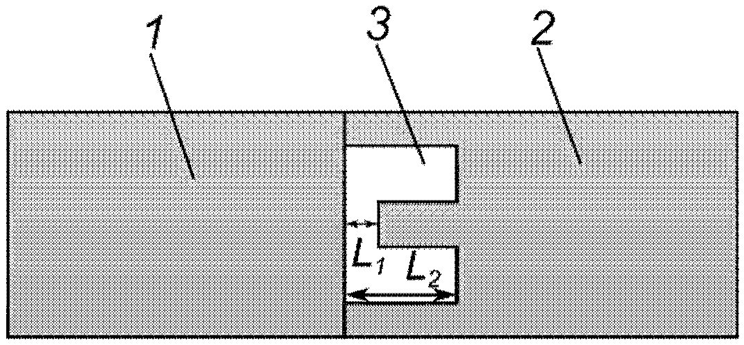
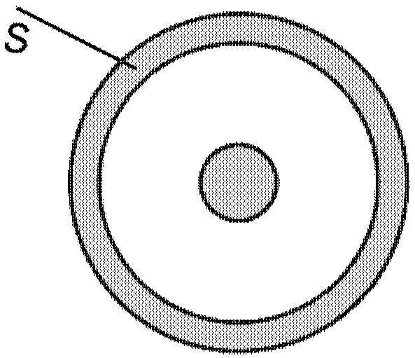
[0028] According to the basic idea of ​​the present invention, by adopting laser to directly process the end face of the first optical fiber and or the second optical fiber, an annular groove is m...


PUM


Abstract

The invention discloses a strain sensor based on an optical fiber Fabry-Perot cavity and a manufacturing method thereof, which belong to the technical field of optical fiber sensors. The sensor comprises a first optical fiber with a first end surface and a second optical fiber with a second end surface; the first end surface and the second end surface are in butt joint to form the Fabry-Perot cavity; and the Fabry-Perot cavity is internally provided with an air gap. According to the sensor with the microcavity structure in the design, the strain measurement sensitivity of the optical fiber strain sensor is greatly improved, and the temperature strain cross sensitivity is extremely low.

Description

technical field [0001] The invention belongs to the technical field of optical fiber sensing, and in particular relates to a strain sensor based on an optical fiber Fabry-Perot cavity and a manufacturing method thereof, and also relates to a sensor device including the above-mentioned strain sensor. Background technique [0002] Optical fiber sensing has the characteristics of miniaturization, anti-electromagnetic interference, corrosion resistance, and many physical quantities that can be measured. It has been extensively studied and applied in engineering technology and scientific research. Its measurement objects include: displacement, pressure, strain, current, voltage, gas, vibration, and acceleration, etc., where strain refers to the ratio of the deformation of an object under the action of an external force to the length of the object. At present, optical fiber-based strain sensing has been widely used in many fields, such as structural safety monitoring and early war...

Claims


Application Information

Patent Timeline
Patent Type & Authority Applications(China)
IPC IPC(8): G01D5/353G01B11/16G01B9/02
CPCG01B9/02G01B11/161G01D5/35312
Inventor 周坤崔金明黄运锋李传峰
Owner UNIV OF SCI & TECH OF CHINA
Why Eureka
Try Eureka