Self aligning-type permanent magnet coupling

A permanent magnet coupling, medium-sized technology, applied in the field of mechanical transmission, can solve the problem of eccentric adsorption of two permanent magnet rotors, and achieve the effect of ensuring relative uniformity, long service life and refined structure

Pending Publication Date: 2018-10-23
JIANGSU MAGNET VALLEY TECH
View PDF11 Cites 5 Cited by
  • Summary
  • Abstract
  • Description
  • Claims
  • Application Information

AI Technical Summary

Problems solved by technology

[0005] The technical problem to be solved by this patent is to overcome the eccentric adsorption and alignment problems of the two permanent magnet rotors existing in the synchronous permanent magnet coupling in the prior art

Method used


Image

  • Self aligning-type permanent magnet coupling
  • Self aligning-type permanent magnet coupling
  • Self aligning-type permanent magnet coupling

Examples


Embodiment 1

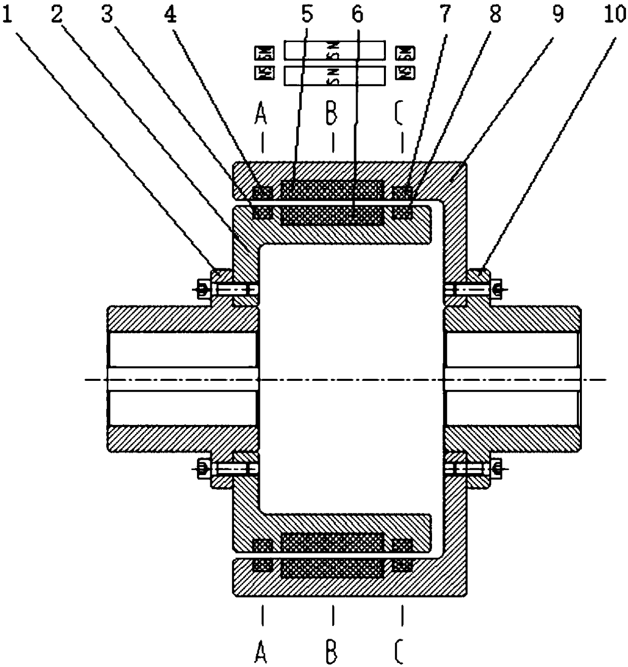
[0031] Such as figure 1 As shown, the self-centering permanent magnet coupling is mainly composed of an inner rotor flange bushing 1, a magnetic coupling body, and an outer rotor flange bushing 10, wherein the magnetic coupling body is composed of an inner permanent magnet rotor and an outer permanent magnet The magnetic coupling part composed of the rotor; the inner permanent magnet rotor includes the inner rotor carrier 2, the inner rotor suspension magnets 3, 8 and the inner rotor permanent magnet magnet 6; the outer permanent magnet rotor includes the outer rotor carrier 9, the outer rotor suspension magnet Steel 4,7 and outer rotor permanent magnet magnet steel 5.

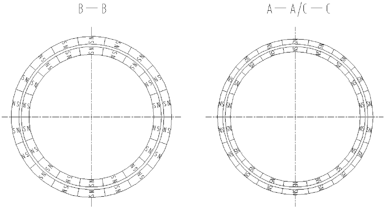
[0032] The outer rotor permanent magnetic steel 5 and the inner rotor permanent magnetic steel 6 are respectively arranged in the middle of the outer rotor carrier 9 and the inner rotor carrier 2. The magnetic circuit adopts N-S magnetic pole alternate arrangement or Halbach array structure to form a magnetic ...

Embodiment 2

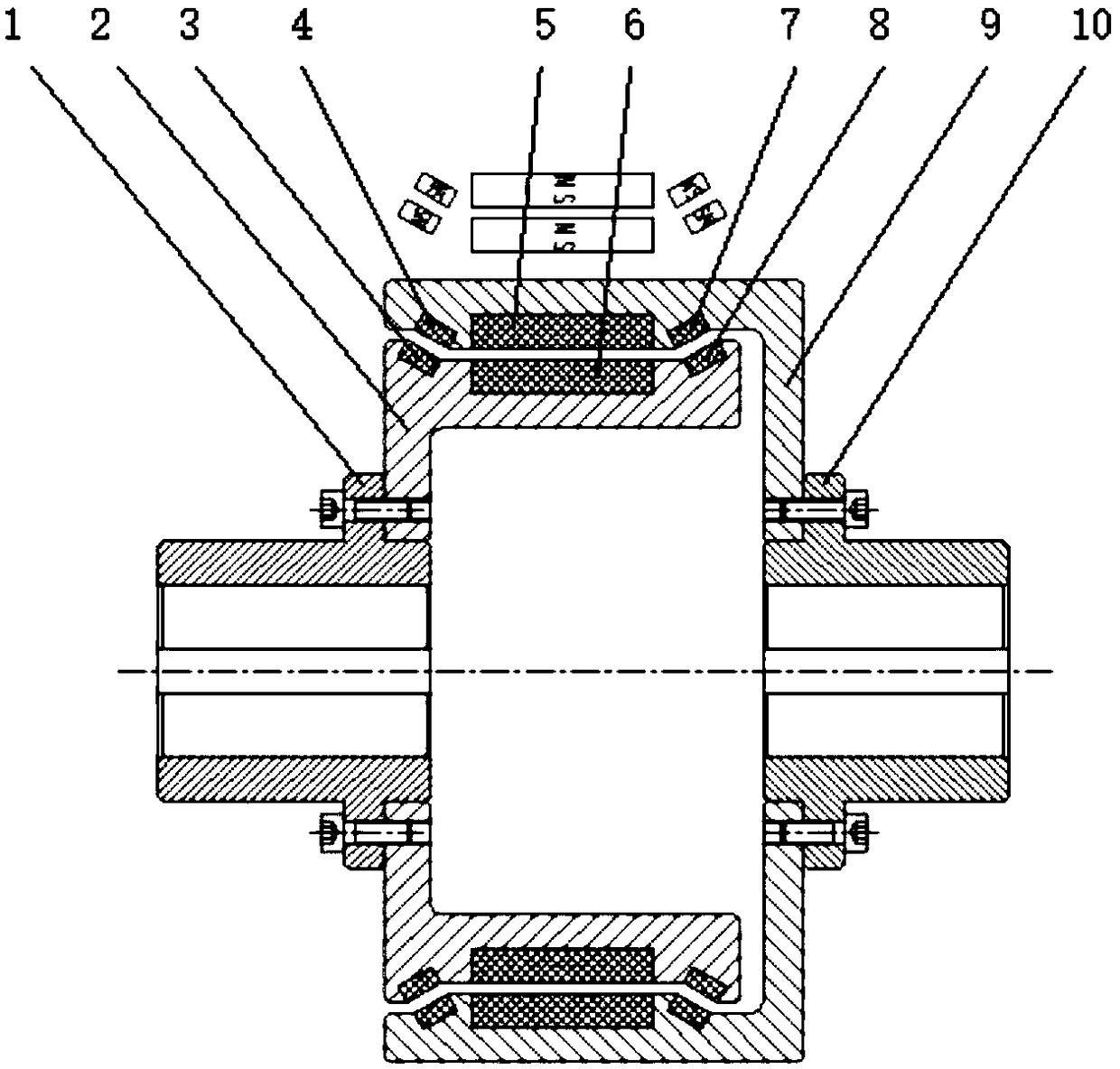
[0039] This patent has another preferred self-aligning permanent magnet coupling, such as figure 2 As shown, its structural difference from Embodiment 1 is that the outer rotor suspension magnets 4, 7 and the inner rotor suspension magnets 3, 8 are respectively arranged at the two ends of the outer rotor carrier 9 and the inner rotor carrier 2, and the two rotor magnets are inclined Arranged in parallel at a certain angle, relying on the magnetic repulsion of N-N poles or S-S poles makes the two permanent magnet rotors in a radial and axial suspension state.

Embodiment 3

[0041]This patent has yet another preferred self-centering permanent magnet coupling, wherein the outer rotor carrier is a split structure, including two outer rotor suspension magnetic steel carrier parts for respectively arranging two outer rotor suspension magnetic steels, and The outer rotor permanent magnet carrier part of the outer rotor permanent magnet magnet is provided, the outer rotor permanent magnet carrier part is located between the two outer rotor suspension magnet carrier parts, and the outer rotor permanent magnet carrier part is connected to the two outer rotor permanent magnet carrier parts. The rotor suspension magnetic steel carrier parts are rigidly connected to form an integrated structure.


PUM


Abstract

The invention relates to a self aligning-type permanent magnet coupling, which mainly comprises an inner rotor flange shaft sleeve, a magnetic coupling body and an outer rotor flange shaft sleeve. According to the magnetic coupling body, due to magnetic attraction coupling effects of N-S poles of permanent magnet magnetic steels arranged by an inner permanent magnet rotor and an outer permanent magnet rotor, the permanent magnet coupling can thus transfer torque. Besides, the magnetic coupling body is additionally provided with permanent magnet levitation magnet steels, through mutual repulsion effects of N-N poles or S-S poles, the two permanent magnet rotors are in a magnet levitation state radially or both radially and axially, the relative uniformity of radially-coupled magnetic steelair gaps can be ensured, and the technical difficult problem that the two permanent magnet rotors are eccentric and are absorbed together due to factors such as assembly errors, mounting errors and uneven force applying in the case of mounting can be solved.

Description

technical field [0001] This patent relates to the technical field of mechanical transmission, in particular to a self-aligning permanent magnet coupling. Background technique [0002] Permanent magnetic couplers are increasingly used in mechanical transmission systems due to their characteristics such as no need for precise alignment during installation, good vibration isolation and vibration reduction effects, small post-maintenance workload, simple structure, and suitable for various harsh working conditions. get applied. The synchronous permanent magnet coupling is mainly composed of an active permanent magnet rotor and a driven permanent magnet rotor, which also includes a disc structure and a cylinder structure. [0003] The axial force of the disc structure permanent magnet coupling is relatively large. In order to avoid additional axial force after installation, generally more cylindrical structures are used, that is, the two permanent magnet rotors participate in th...

Claims


Application Information

Patent Timeline
Patent Type & Authority Applications(China)
IPC IPC(8): H02K49/10H02N15/00
CPCH02K49/106H02K49/108H02N15/00
Inventor 徐俊峰牟红刚
Owner JIANGSU MAGNET VALLEY TECH
Why Eureka
Try Eureka