A Path Planning Method for High Energy Beam Moving Front Machining

A processing path and high-energy beam technology, applied in metal processing equipment, manufacturing tools, auxiliary welding equipment, etc., to achieve the effect of improving milling accuracy, improving processing accuracy and quality, and reducing pores and defects

Active Publication Date: 2019-06-28
HUAZHONG UNIV OF SCI & TECH
View PDF9 Cites 0 Cited by
  • Summary
  • Abstract
  • Description
  • Claims
  • Application Information

AI Technical Summary

Problems solved by technology

[0006] At present, the public processing path planning schemes mainly focus on improving the processing efficiency by shortening the auxiliary processing path, optimizing the processing path to improve the quality of the splicing area in the layer, or discrete processing paths in time and space to reduce the thermal impact. In-layer planning processing path

Method used


Image

  • A Path Planning Method for High Energy Beam Moving Front Machining
  • A Path Planning Method for High Energy Beam Moving Front Machining
  • A Path Planning Method for High Energy Beam Moving Front Machining

Examples


Embodiment Construction

[0026] In order to make the object, technical solution and advantages of the present invention clearer, the present invention will be further described in detail below in conjunction with the accompanying drawings and embodiments. It should be understood that the specific embodiments described here are only used to explain the present invention, not to limit the present invention. In addition, the technical features involved in the various embodiments of the present invention described below can be combined with each other as long as they do not constitute a conflict with each other.

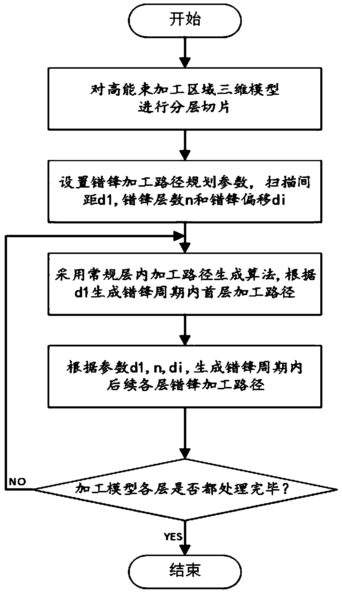
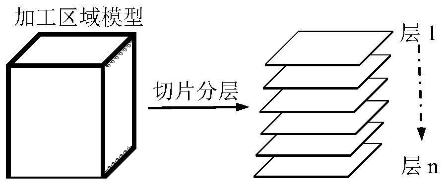
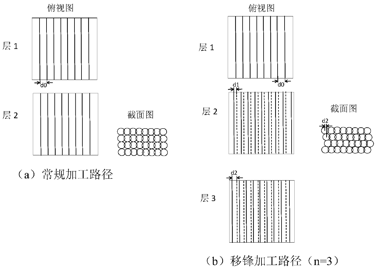
[0027] Aiming at the characteristics of uneven energy distribution in high-energy beam processing, the present invention proposes a method of applying front-shifting processing rules when generating multi-layer scanning paths, so that the peaks of high-energy beams are staggered from each other within several adjacent layers during processing, thereby improving processing The energy distribution...


PUM


Abstract

The invention discloses a high-energy beam peak moving processing path planning method and belongs to the technical field of high-energy beam manufacturing. According to the high-energy beam peak moving processing path planning method, when filling scanning paths of various to-be-processed layers are generated, between the adjacent various layers, positions, highest in power, in the high-energy beam scanning paths mutually deviate by set amounts, and therefore energy distribution in the processing process is improved, and then the processing quality and precision in the additive manufacturingor subtractive manufacturing process are improved; the method includes the following steps that firstly, a processing model is subjected to layering; secondly, peak moving processing path planning parameters are set; thirdly, a processing path of a first layer in the peak moving period is generated; fourthly, processing paths of subsequent various layers in the peak moving period are generated; and fifthly, the step (3) and the step (4) are repeated till the processing paths of all the layers are generated. According to the method, by adjusting the center position deviation of the high-energybeam scanning paths of the adjacent processing layers, that is, a pointed peak is moved away, peak moving for short, energy density homogenization of processing of the plurality of layers is achieved,and the processing quality and precision are improved.

Description

technical field [0001] The invention belongs to the technical field of high-energy beam manufacturing, and relates to laser milling (also known as laser etching), laser additive manufacturing, arc additive manufacturing, ion beam processing, electron beam processing and other high-energy beam additive and subtractive manufacturing technologies, specifically In order to improve the quality and precision of high energy beam processing in additive and subtractive manufacturing through the path planning method of high energy beam shifting front. Background technique [0002] Additive and subtractive manufacturing technologies that use high-energy beams such as laser beams, electron beams, ion beams, and electric arcs as tools, apply high-power-density energy beams to materials, and make materials melt and accumulate (additive manufacturing) or gasify and remove ( Subtractive manufacturing), has the advantages of non-contact processing, adjustable power, no tool wear, easy transm...

Claims


Application Information

Patent Timeline
Patent Type & Authority Patents(China)
IPC IPC(8): B23K37/00
CPCB23K37/00
Inventor 蒋明李旸曾晓雁
Owner HUAZHONG UNIV OF SCI & TECH
Why Eureka
Try Eureka