Thermal management of hybrid commercial vehicles using a dynamic heat generator

A heat generator, hybrid electric technology, used in hybrid vehicles, traction using an engine, the arrangement of multiple different prime movers of a general power plant, etc., can solve the requirement of less or no front length extension And other issues

Active Publication Date: 2022-03-25
BENDIX COMML VEHICLE SYST LLC
View PDF15 Cites 0 Cited by
  • Summary
  • Abstract
  • Description
  • Claims
  • Application Information

AI Technical Summary

Problems solved by technology

[0010] The present invention addresses these and other problems by providing a hybrid electric vehicle system that is positioned at the front end of the engine with the motor generator arranged in a manner that requires little or no lengthening of the front of the vehicle

Method used


Image

  • Thermal management of hybrid commercial vehicles using a dynamic heat generator
  • Thermal management of hybrid commercial vehicles using a dynamic heat generator
  • Thermal management of hybrid commercial vehicles using a dynamic heat generator

Examples


Embodiment Construction

[0094] Front End Motor Generator System Embodiment.

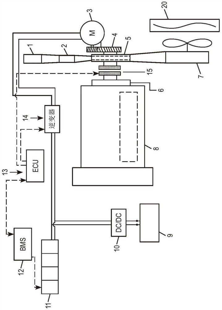
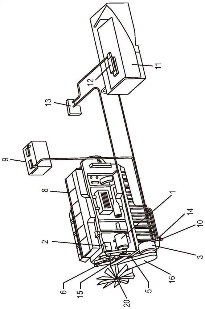
[0095] Figure 1A is a schematic diagram showing the components of an embodiment of a FEMG system according to the present invention. Figure 1B is a schematic diagram of several FEMG system components in the chassis of a commercial vehicle. In this arrangement, the engine accessories (including the gas compressor 1 , the air conditioner compressor 2 and the engine cooling fan 7 arranged to draw cooling gas through the engine coolant radiator 20 ) are driven by the pulley 5 . The pulley 5 is positioned coaxially with the damper 6 which is directly coupled to the crankshaft of the internal combustion engine 8 . The accessories may be driven directly by the drive belt, or provided with their own on-off or variable speed clutches (not shown) that allow the separately configured accessories to be partially or fully disengaged from the belt drive.

[0096] In addition to the drive accessory drive belt, a pulley 5 is coupled to...


PUM


Abstract

A system and method are provided for hybrid electric internal combustion engine applications in which, in applications such as commercial vehicles, off-highway vehicles, and stationary engine mounts, a motor-generator, narrow switchable coupling, and The torque transfer unit is arranged and positioned in a constrained environment at the front of the engine. Preferably, the motor-generator is positioned laterally offset from the switchable coupling arranged coaxially with the front end of the engine crankshaft. The switchable coupling is an integrated unit of crankshaft shock damper, engine accessory drive pulley and disengageable clutch overlap such that the clutch-pulley-damper unit has the same axial depth as a conventional belt drive pulley and engine damper almost the same. The front end motor generator system includes an electrical energy storage portion that receives electrical energy generated by the motor generator when the coupling portion is engaged. When the coupling is disengaged, the motor generator can use the energy returned from the energy storage to drive the pulley portion of the clutch-pulley-damper to drive the engine accessories, independent of the engine crankshaft.

Description

[0001] This application is a continuation-in-part of US Application Serial No. 15 / 378,139, filed on December 14, 2016, the entire disclosure of which is expressly incorporated herein by reference. technical field [0002] The present invention relates to a hybrid electric vehicle and, in particular, to a system for selectively coupling a hybrid power generation and storage system with an internal combustion engine. The invention further relates to a method of operating the system. Background technique [0003] Hybrid electric vehicles with internal combustion engines combined with motor generators and electrical energy storage systems have become the focus of considerable attention in the automotive sector, especially in the passenger car sector. The development of hybrid electric vehicle systems has only recently begun to generate significant interest in commercial and off-highway vehicles such as trucks and buses in vehicle classes 2-8, earthmoving equipment and railroad a...

Claims


Application Information

Patent Timeline
Patent Type & Authority Patents(China)
IPC IPC(8): B60K11/04B60W10/06B60W10/08B60W10/26B60W20/00F01P5/10B60L50/15B60L50/16
CPCB60K11/04B60W10/06B60W10/08B60W10/26B60W20/00F01P5/10B60K6/387B60K11/02B60H1/03H02K7/1008H02K7/112H02K7/14H02K7/1815B60L50/15B60L50/16B60K2025/022B60H1/00378B60H1/004B60H1/143B60K6/485B60L50/64Y02T10/64Y02T10/7072Y02T10/62
Inventor 大卫·科拉纹森佐
Owner BENDIX COMML VEHICLE SYST LLC
Why Eureka
Try Eureka