Solar aerator with high stability

A stable performance, solar energy technology, applied in water aeration, electrical components, polluted waterway/lake/pond/river treatment, etc., can solve problems such as increased cost, damage to solar panels, dumping, etc., to extend service life , Improve stability, scientific and reasonable structure

Inactive Publication Date: 2018-10-26
安徽中疆数字科技有限公司
View PDF6 Cites 5 Cited by
  • Summary
  • Abstract
  • Description
  • Claims
  • Application Information

AI Technical Summary

Problems solved by technology

[0003] The present invention provides a solar aerator with high stability, which can effectively solve the problem that the solar panels of the existing solar aerator proposed in the above background technology are directly fixed and installed above the solar panel bracket above the floating bed. When transporting, because the solar panel is supported by the bracket, it will cause overall instability, and it will inevitably touch the edge of the solar panel, which may cause damage to the solar panel. When the inverted umbrella impeller is driven by the drive motor, the drive The motor will produce a lot of vibration. Since the solar aerator is installed on the water surface, the vibration generated when driving the motor may cause the solar aerator to be unstable or even topple over. The solar panel converts solar energy into electrical energy. And stored in the lithium-ion battery, the lithium-ion battery will generate heat during the discharge process. If the heat generated by the lithium-ion battery is not dissipated, the service life of the lithium-ion battery will be reduced and the cost of water environment treatment will be increased. When solar energy is exposed When the air machine is placed in a shallow lake, the rotation of the inverted umbrella-shaped impeller may cause the silt at the bottom of the lake to surge, causing the entire lake to be dirty. If only the solar aerator is used to increase the oxygen content in the water and improve the self-efficacy of the water body Purification ability will prolong the time of water environment treatment

Method used


Image

  • Solar aerator with high stability
  • Solar aerator with high stability
  • Solar aerator with high stability

Examples


Embodiment

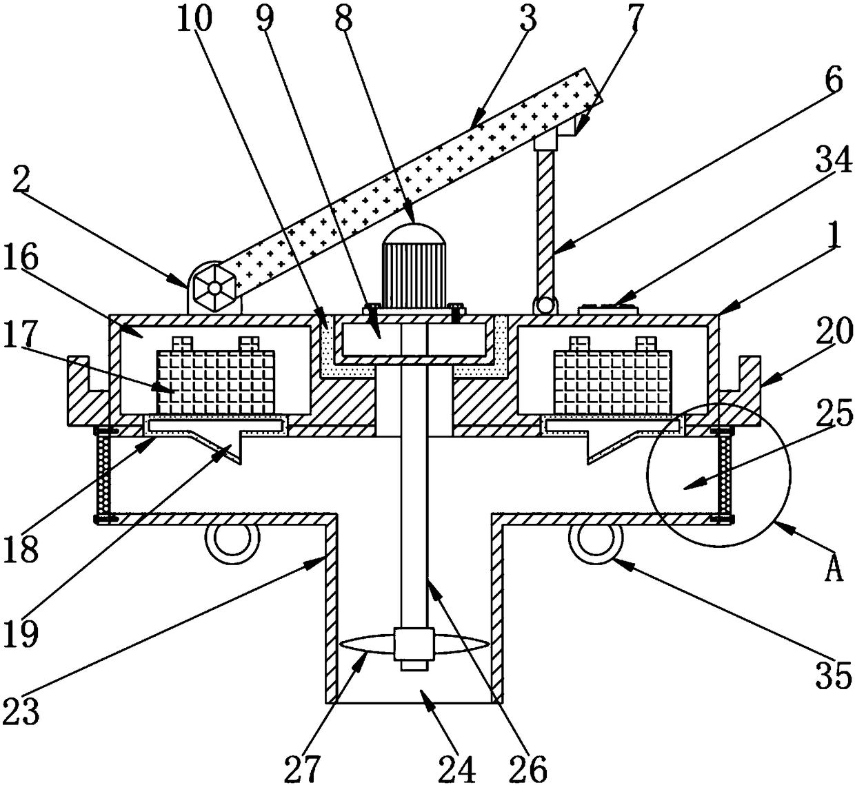
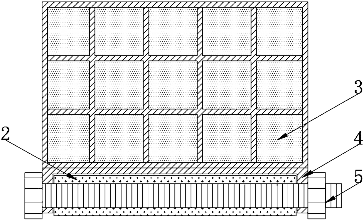
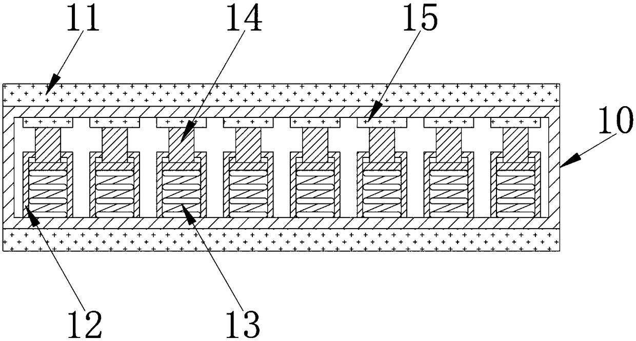
[0029] Example: such as Figure 1-6As shown, the present invention provides a technical solution, a solar aerator with high stability, including a floating bed 1, a fixed shaft 2, a solar panel 3, a fixed ear 4, a fixed screw 5, a support rod 6, and a limit block 7. Drive motor 8, gear reduction box 9, shock absorbing plate 10, shock absorbing rubber pad 11, sleeve 12, shock absorbing spring 13, sleeve rod 14, shock absorbing rubber seat 15, power chamber 16, lithium-ion battery 17 , cooling box 18, first water inlet 19, first installation ear 20, second installation ear 21, external floating bed 22, T-shaped water pipe 23, second water inlet 24, water outlet 25, rotating shaft 26, inverted umbrella type Impeller 27, filter screen plate 28, fixing screw 29, permeable hole 30, filter screen 31, mounting plate 32, handle 33, control switch 34 and positioning fixed ring 35, one end above floating bed 1 is welded with fixed shaft 2, and fixed shaft 2 is inclined The solar cell pa...


PUM


Abstract

The invention discloses a solar aerator with high stability. The solar aerator with high stability comprises a damping plate, damping rubber pads, a sleeve, a damping spring, a loop bar and a dampingrubber seat, wherein the damping rubber pads are separately attached to the upper surface and the lower surface of the damping plate; the bottom end of the inside of the damping plate is welded to thesleeve; the damping spring is mounted in the sleeve; the loop bar is inserted in the top end of the inside of the sleeve; and the damping rubber seat is attached to the top end of the loop bar. The solar aerator with high stability is scientific and reasonable in structure and safe and convenient to use, and is provided with the damping plate, the damping rubber pads, the sleeve, the damping spring, the loop bar and the damping rubber seat, in a working process of the driving motor, the damping spring is extruded by the loop bar, influences of vibration generated in the working process of thedriving motor to a whole floating bed can be relieved effectively, the stability of the floating bed on the water surface can be improved effectively, the circumstance that the floating bed is inclined and then falls can be prevented effectively, and the service life of the solar aerator is prolonged.

Description

technical field [0001] The invention relates to the technical field of water environment, in particular to a solar aerator with high stability. Background technique [0002] The solar aerator uses solar energy as the direct driving force for the operation of the equipment. It is equipped with a unique rotary cutting and lifting aeration impeller. Through the rotation and lifting of the impeller, the anoxic water at the bottom is transferred to the surface of the water body and mixed with the oxygen-enriched water on the surface. Water diffuses horizontally and horizontally through centrifugal rotation, and enters the anoxic zone at the bottom layer vertically, thereby realizing the triple effect of water body delamination, oxygenation, and vertical and horizontal circulation and exchange, and maximizing the transfer of supersaturated dissolved oxygen water from the surface to the bottom of the water body, increasing the bottom water body. Dissolved oxygen, eliminate natural ...

Claims


Application Information

Patent Timeline
Patent Type & Authority Applications(China)
IPC IPC(8): C02F7/00C02F9/02F16F15/04H02J7/35
CPCC02F1/001C02F1/28C02F7/00C02F9/00C02F2103/007C02F2201/009F16F15/04H02J7/35Y02W10/10
Inventor 王兴生
Owner 安徽中疆数字科技有限公司
Why Eureka
Try Eureka