High-altitude live working robot and operation method thereof

A technology for live work and robots, applied in manipulators, program-controlled manipulators, manufacturing tools, etc., can solve problems such as inability to achieve work, increased labor intensity, and complex operating environments, achieve a wide range of work adaptation, reduce accidents, and labor. Intensity requires little effect

Pending Publication Date: 2018-10-30
XUZHOU HANDLER SPECIAL VEHICLE
View PDF26 Cites 5 Cited by
  • Summary
  • Abstract
  • Description
  • Claims
  • Application Information

AI Technical Summary

Problems solved by technology

The defect of this robot device is: 1), its operation manipulator adopts motor drive, and manipulator adopts hydraulic drive, but the generator and the hydraulic pump that provide power source are installed on the automobile chassis, can only be dragged long wire and The oil pipe is connected to the working manipulator arm and manipulator, so that the working insulating support platform is at the same potential as the car chassis, which is very easy to cause the insulating platform to be grounded, so there is a great potential safety hazard; 2). The environment is relatively complex, and this kind of manipulator has poor adaptability in such complex lines
The disadvantages of this kind of robot are: 1), the operator of this kind of robot still needs to stand in the insulating bucket at the end of the arm when working with live electricity. Although he does not directly contact the high-voltage line for work, the distance between the high-voltage line and the high-voltage line is relatively close, and it also belongs to high-altitude work; Moreover, the efficiency and accuracy of the operator's indirect operation by manipulating the mechanical arm is much lower than that of manual direct operation; at the same time, the time for the operator to work at high altitude will be longer, and the labor intensity will increase; 2). , so the requirements for the insulation protection of the platform and the manipulator are particularly high, and the manipulator needs power to drive, only relying on insulating sleeves or insulators and the distance between the structural parts cannot fully ensure a safe insulation gap, which is likely to cause safety hazards; 3) 1. The position adjustment of the work platform is mainly realized by controlling the lower arm luffing, upper arm luffing, upper arm telescoping, and turret rotation of the vehicle. Under the complex high-voltage line, the bucket end vibration is easily caused by the macroscopic movement of each boom, so It is impossible to realize the precise positioning of the operation platform, and it is easy to accidentally touch the high-voltage wires, causing potential safety hazards; 4), the operation platform is large, and the operation flexibility of the operation platform is poor, and the operation can only be carried out in the inner phase of the high-voltage line. It is impossible to realize the operation with the outside and the outside, and the adaptability of the work space is poor

Method used


Image

  • High-altitude live working robot and operation method thereof
  • High-altitude live working robot and operation method thereof
  • High-altitude live working robot and operation method thereof

Examples


Embodiment 1

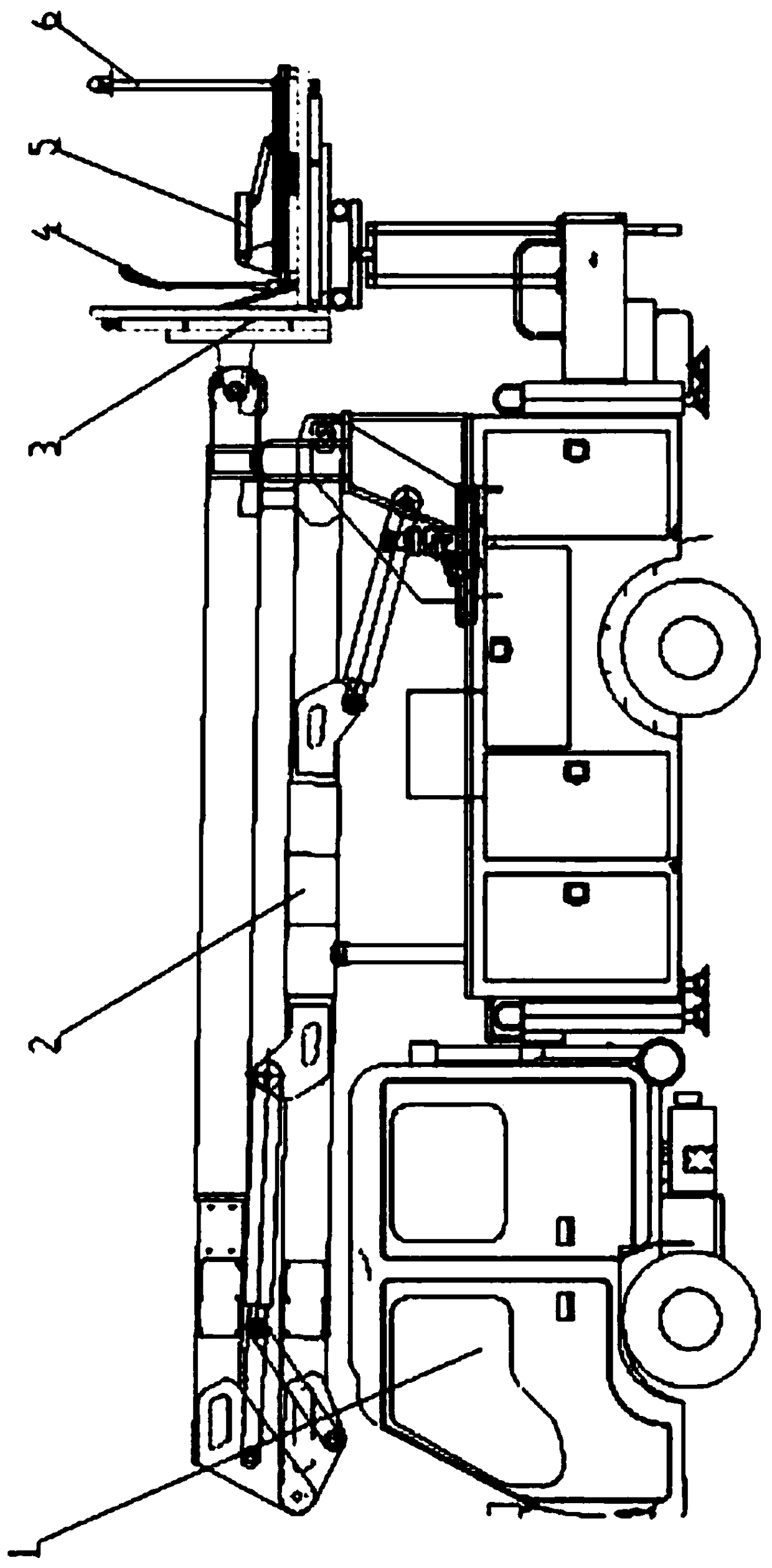
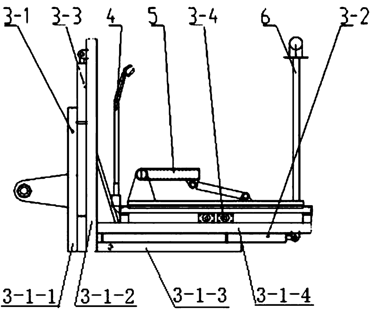
[0033] like Figure 1 to Figure 3 As shown, a high-altitude live working robot includes a mobile chassis 1, a macro arm frame 2, a micro-motion platform 3 and a leveling system. The macro-motion arm frame 2 is installed on the upper end of the mobile chassis 1, and the micro-motion platform 3 is set on the macro-motion The arm end of the jib 2, the macro-moving jib 2 can realize the amplitude-changing, stretching and rotating actions of the jib, and the leveling system is used to control the micro-moving platform to always be in a state parallel to the ground; it is characterized in that the micro-moving platform 3 Including the main frame 3-1 and the moving platform 3-8, the moving platform 3-8 is installed on the main frame 3-1 through a three-axis moving mechanism, and the three-axis moving mechanism can realize the moving platform relative to the main frame X axis, Y Axis and Z-axis movement in three directions; the upper end of the moving platform 3-8 is provided with a t...

Embodiment 2

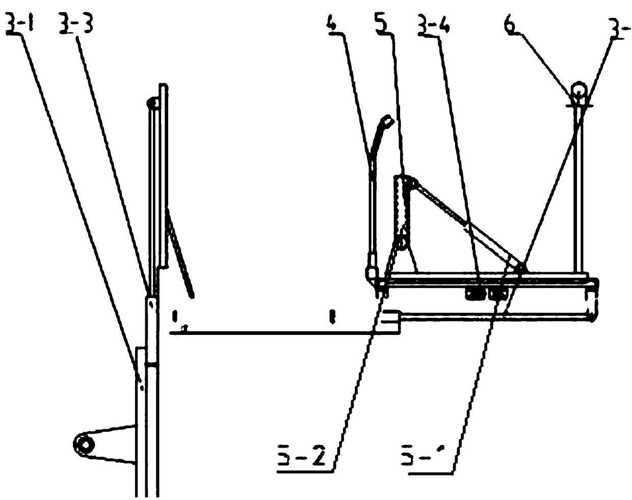
[0049] like Figure 4 As shown, the difference from Embodiment 1 is that the three-axis moving mechanism also includes an X-axis turning mechanism 3-7, a Y-axis turning mechanism 3-5 and a Z-axis turning mechanism 3-6, and the X-axis turning mechanism 3- The rotary end of 7 links to each other with vertical support frame one 3-1-1, and the fixed end of X-axis rotary mechanism 3-7 is fixed on the support one 3-9; The rotary end of Z-axis rotary mechanism 3-6 is connected with the support One 3-9 is connected, the fixed end of the Z-axis rotary mechanism 3-6 is connected with the rotary end of the Y-axis rotary mechanism 3-5, and the fixed end of the Y-axis rotary mechanism 3-5 is connected with the support two 3-10.

[0050] Other structures are the same as in Embodiment 1.

[0051] Utilize the X-axis rotary mechanism 3-7, the Y-axis rotary mechanism 3-5 and the Z-axis rotary mechanism 3-6 to respectively control the micro-motion platform 3 to rotate around the X-axis, Y-axis ...


PUM


Abstract

The invention discloses a high-altitude live working robot and an operation method thereof. The robot comprises a mobile chassis, a macro movable arm rest, a micro-motion platform and a leveling system. The micro-motion platform comprises a main frame and a mobile platform. The mobile platform is mounted on the main frame through a three-axis moving mechanism. The three-axis moving mechanism can implement movement of the mobile platform relative to the X-axis, the Y-axis and the Z-axis of the main frame. A turnover seat capable of turning over by 90 degrees is arranged at the upper end of themobile platform. An insulating operating bar is arranged on the turnover seat. A manipulator is mounted at the rear end of the mobile platform. The front end of the mobile platform is provided with acamera. A center console is arranged on the ground. The camera feeds back the photographed conditions to the center console in real time. The center console controls actions of the manipulator throughsignals. The high-altitude live working robot is applicable to various types of complex lines such as star-shaped lines and parallel lines, good in insulating property, high in safety coefficient, capable of accurately locating operation points and also capable of reducing the labor intensity of operating personnel and improving the working efficiency.

Description

technical field [0001] The invention relates to a high-altitude working robot, in particular to a high-altitude live-working robot and an operation method, which belong to the technical field of high-altitude live working. Background technique [0002] At present, the live working method adopts the insulating rod operation method. The principle is ground potential operation. The operator stands on the ground and operates the insulating rod to work on the overhead line. This operation method has the advantages of high labor intensity, low safety, and limited operating height. The shortcoming of low efficiency; there is another way is to use the insulated bucket arm truck for operation, the operator operates the insulated bucket arm truck close to the charged body, the operator stands in the insulating bucket, wears protective clothing, and wears three layers of gloves on the charged body. The operation is an intermediate potential operation method, and the efficiency has been...

Claims


Application Information

Patent Timeline
Patent Type & Authority Applications(China)
IPC IPC(8): B25J5/00B25J9/00
CPCB25J5/007B25J9/00
Inventor 郑磊马超李培启
Owner XUZHOU HANDLER SPECIAL VEHICLE
Why Eureka
Try Eureka