Millimeter wave differential feeding dual-polarized electromagnetic dipole antenna

An electromagnetic dipole and differential feeding technology, which is applied in the microwave field, can solve problems such as differential feeding dual-polarized electromagnetic dipole antennas, and achieve the effects of small cost and weight, easy processing, and improved integration

Active Publication Date: 2018-10-30
HANGZHOU DIANZI UNIV
View PDF3 Cites 33 Cited by
  • Summary
  • Abstract
  • Description
  • Claims
  • Application Information

AI Technical Summary

Problems solved by technology

[0005] At present, there are no related reports on the implementation of differentially fed dual-po

Method used


Image

  • Millimeter wave differential feeding dual-polarized electromagnetic dipole antenna
  • Millimeter wave differential feeding dual-polarized electromagnetic dipole antenna
  • Millimeter wave differential feeding dual-polarized electromagnetic dipole antenna

Examples


Embodiment Construction

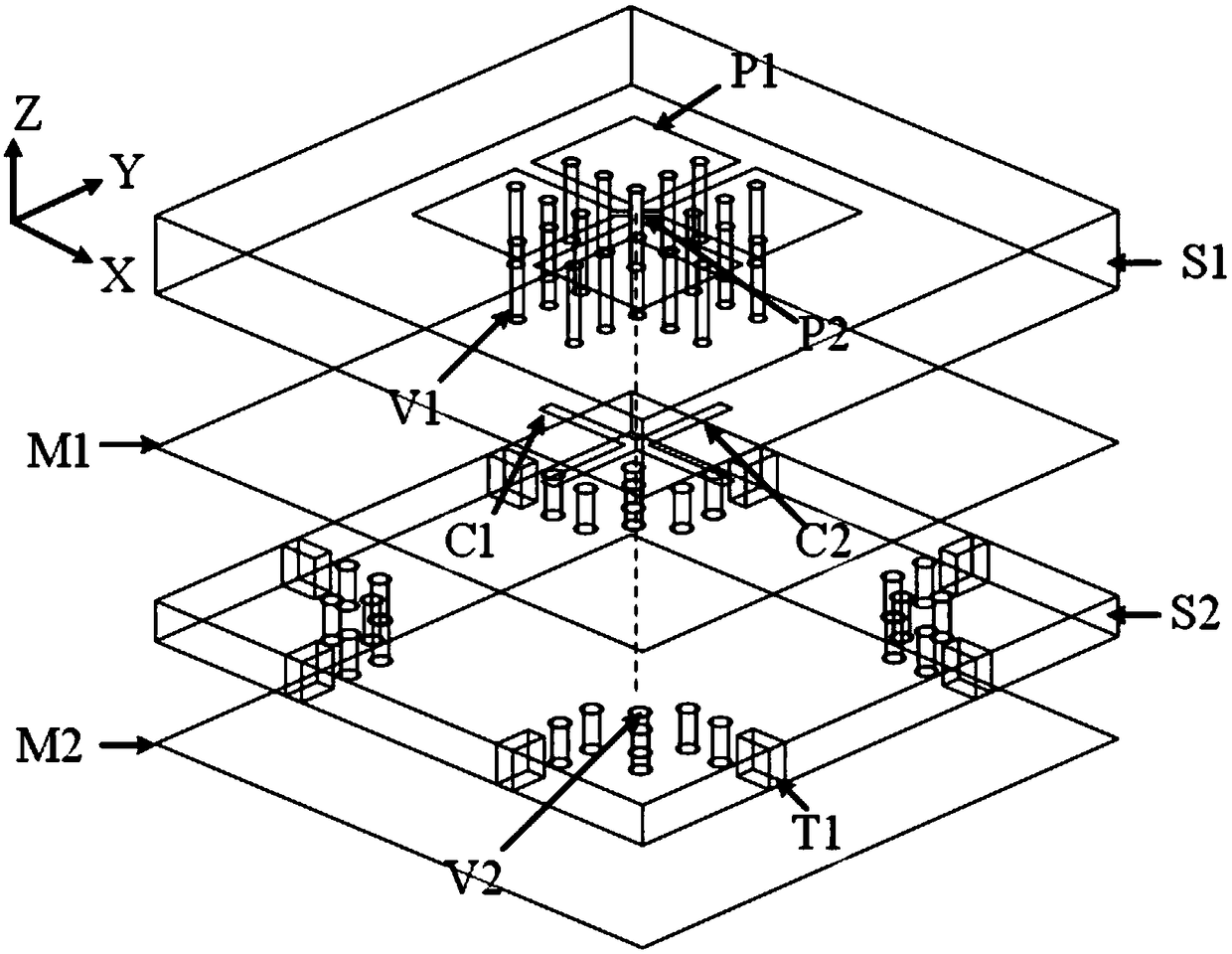
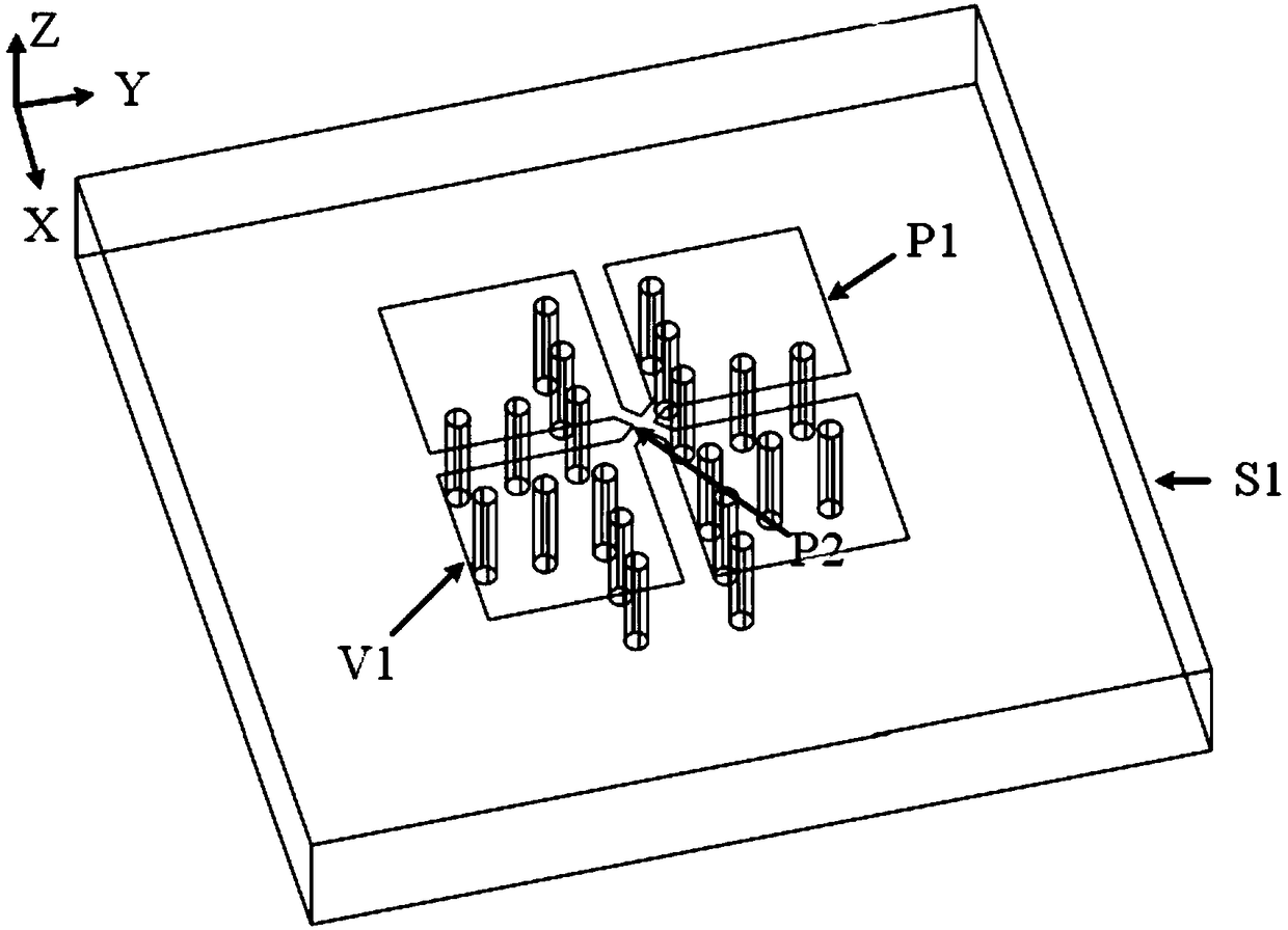
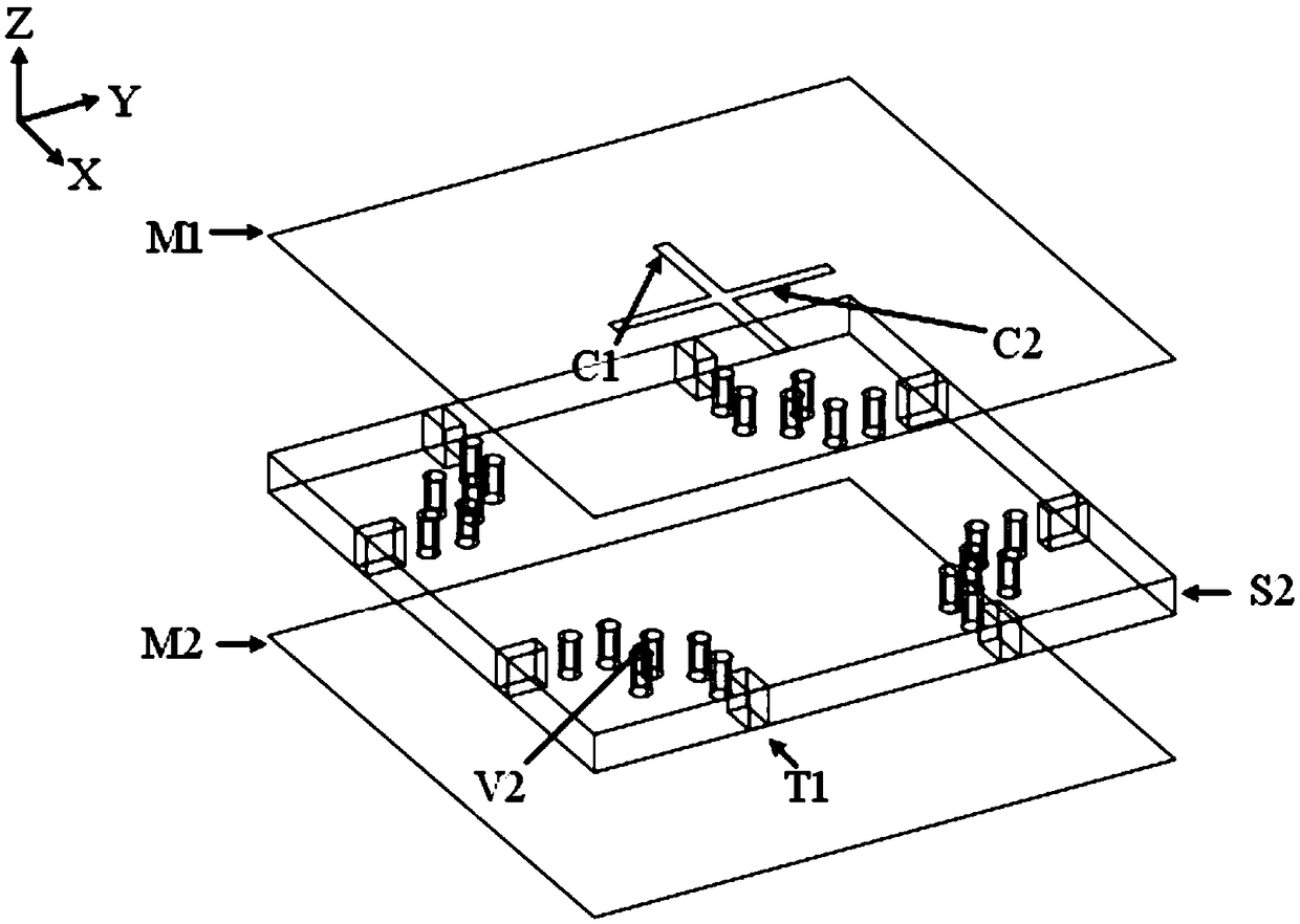
[0035] The present invention will be described in further detail below in conjunction with the accompanying drawings. combine figure 1 , figure 2 , image 3 , a millimeter-wave differentially fed dual-polarized electromagnetic dipole antenna, characterized in that it includes a rectangular radiation patch P1, a cross-shaped connection structure P2, a first dielectric substrate S1, a second dielectric substrate S2, and a first metal layer M1 , the second metal layer M2, the first coupling slot C1, the second coupling slot C2, the SIW structure T1, the first metal pillar V1, and the second metal pillar V2;

[0036] The first dielectric substrate S1 is on the upper layer, and the second dielectric substrate S2 is on the lower layer. The rectangular radiation patch P1 and the cross-shaped connection structure P2 are located on the upper surface of the first dielectric substrate S1, and the cross-shaped connection structure P2 connects four rectangular radiation patches. The f...


PUM


Abstract

The invention provides a millimeter wave differential feeding dual-polarized electromagnetic dipole antenna. The traditional dual-polarized dipole antenna is poor in port isolation and complex in structure, and is not applicable to the millimeter wave band. According to the millimeter wave differential feeding dual-polarized electromagnetic dipole antenna, a dual-polarized differential feed structure is achieved in a slot coupling manner based on a substrate integration waveguide technology, so that the antenna can work in the millimeter wave band, and has good characteristics including relatively wide working bandwidth and good radiation directional diagram symmetry, the relative bandwidth can reach 28.1%, the cross polarization can be less than -30dB, and the port isolation in the passband can be more than 45dB. In addition, such a structure is machined by using the PCB technology, and is easy to machine and low in cost, and thus the antenna provided by the invention can be mass produced.

Description

technical field [0001] The invention belongs to the field of microwave technology, and relates to a dual-polarized electromagnetic dipole antenna with millimeter wave differential feeding, which can be used as an antenna for radio frequency transceiver front end, and is widely used in mobile communication, satellite communication, radar and other wireless communication systems. Background technique [0002] As the key part of the communication system, the performance of the antenna will directly affect the communication quality of the whole system. Therefore, a high-performance antenna can not only improve the working performance of the entire system and improve transmission efficiency, but also reduce the cost of the entire system and improve economic benefits. [0003] At present, the Ministry of Industry and Information Technology has divided the millimeter wave frequency bands of 24.75GHz to 27.5GHz and 37GHz to 42.5GHz as the working frequency bands of the fifth generat...

Claims


Application Information

Patent Timeline
IPC IPC(8): H01Q1/36H01Q1/38H01Q1/50H01Q9/16H01Q21/00H01Q21/24
CPCH01Q1/36H01Q1/38H01Q1/50H01Q9/16H01Q21/0006H01Q21/24
Inventor 金华燕卜顺秋罗国清俞钰峰代喜望
Owner HANGZHOU DIANZI UNIV
Why Eureka
Try Eureka