
Solar heat and power combined supply system

A technology of combined heat and power and solar energy, applied in the field of photovoltaics, can solve the problems of low heat transfer efficiency, inefficient utilization of heat and electricity, and low power generation efficiency, so as to realize heat conduction and utilization, improve air source heat conversion efficiency, and improve power generation efficiency Effect

Inactive Publication Date: 2018-11-02
SICHUAN SHUANGLV TECH CO LTD
View PDF7 Cites 4 Cited by
  • Summary
  • Abstract
  • Description
  • Claims
  • Application Information

AI Technical Summary

Problems solved by technology

[0006] The technical problems to be solved by the present invention are: the existing photovoltaic modules have low power generation efficiency, the heat transfer medium of the heat collection structure has low heat transfer efficiency during the heat transfer process, and the thermoelectricity is not efficiently utilized

Method used


Image

  • Solar heat and power combined supply system
  • Solar heat and power combined supply system
  • Solar heat and power combined supply system

Examples


Embodiment 1

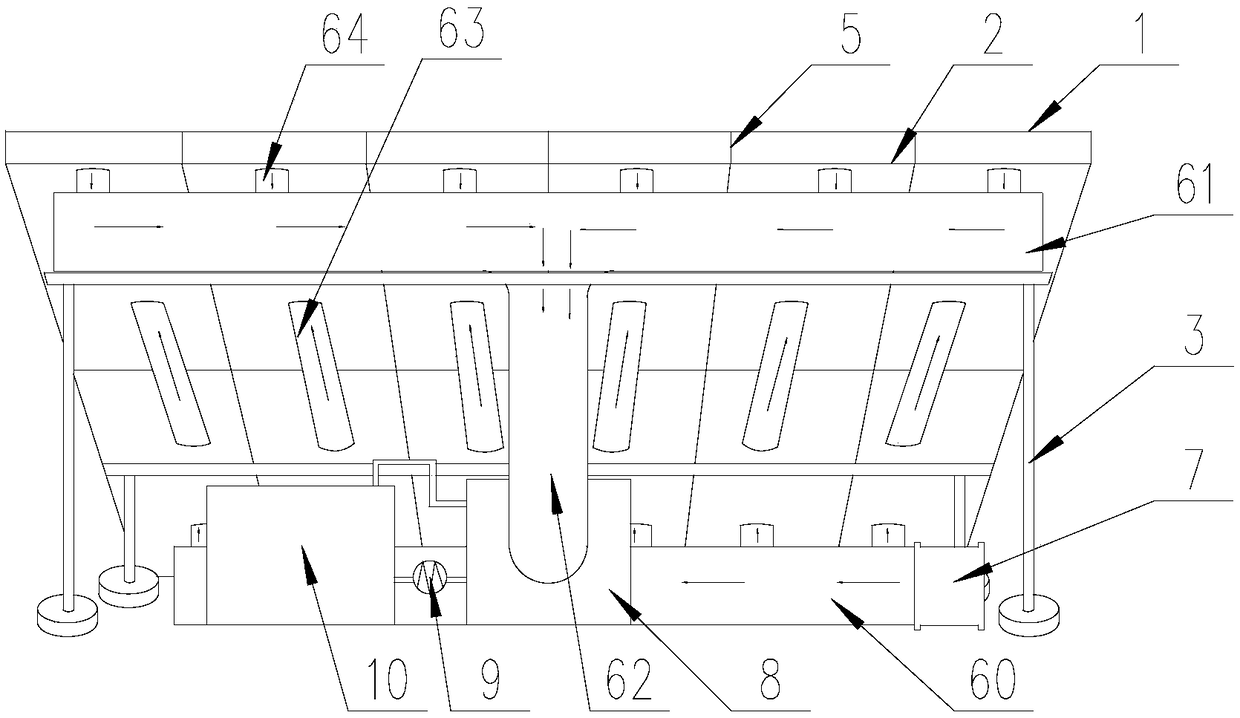
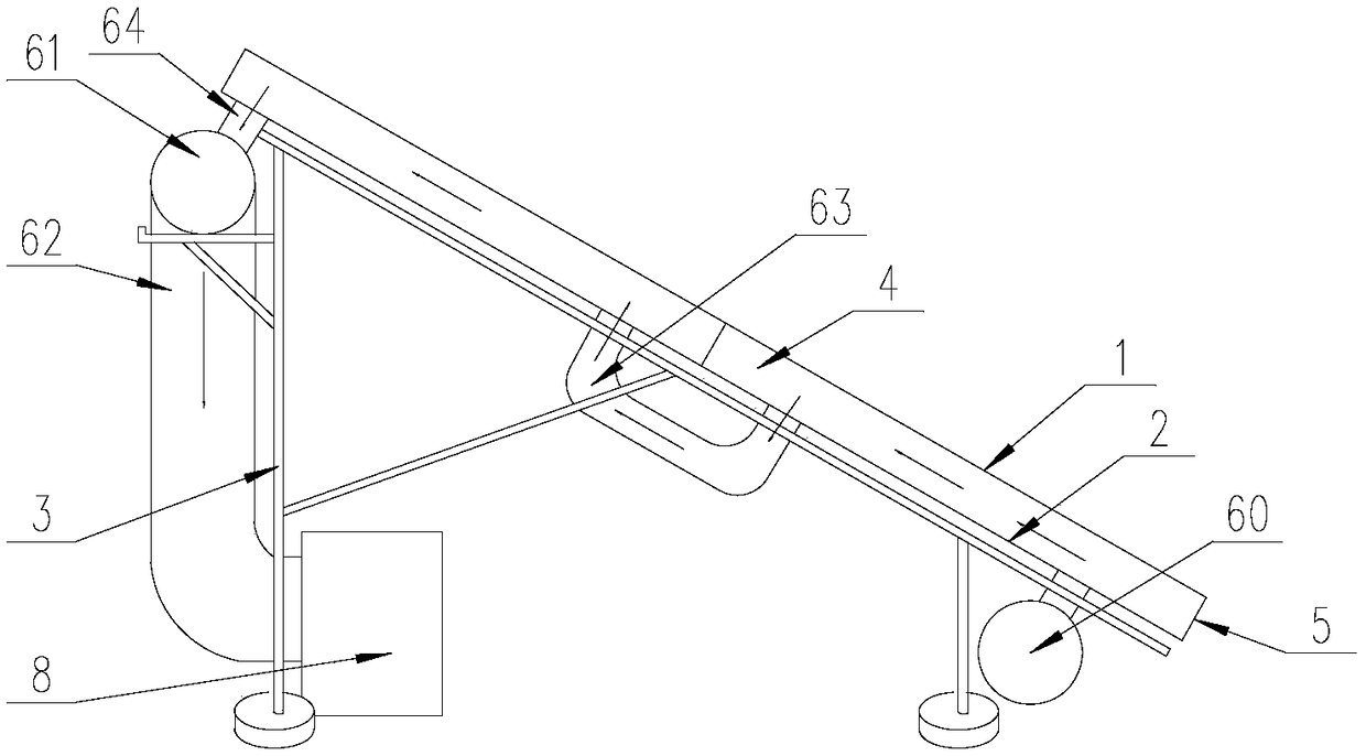
[0030] Such as figure 1 with figure 2 As shown, based on the thermoelectric supply device of the back-collecting photovoltaic module 1, this embodiment is a 3KW system model, which is arranged in 2 series and 6 parallel, including 12 solar battery cells and 12 aluminum-plastic materials. Heat plate 2, the photovoltaic module 1 and the heat collecting plate 2 are installed obliquely on the support frame 3 to form a certain inclination angle, the inclination angle is determined according to the sufficient solar light, the heat collecting plate 2 and the photovoltaic module 1 The heat-conducting frame 5 is connected, the heat-collecting plate 2, the heat-conducting frame 5 and the back of the photovoltaic module 1 are enclosed to form a hollow heat exchange space 4, and each heat-collecting plate 2 is provided with a through hole and a ventilation duct 6 It communicates with the heat exchange space 4 through a through hole, and the vent pipe includes a lower vent pipe 60 arranged ...

Embodiment 2

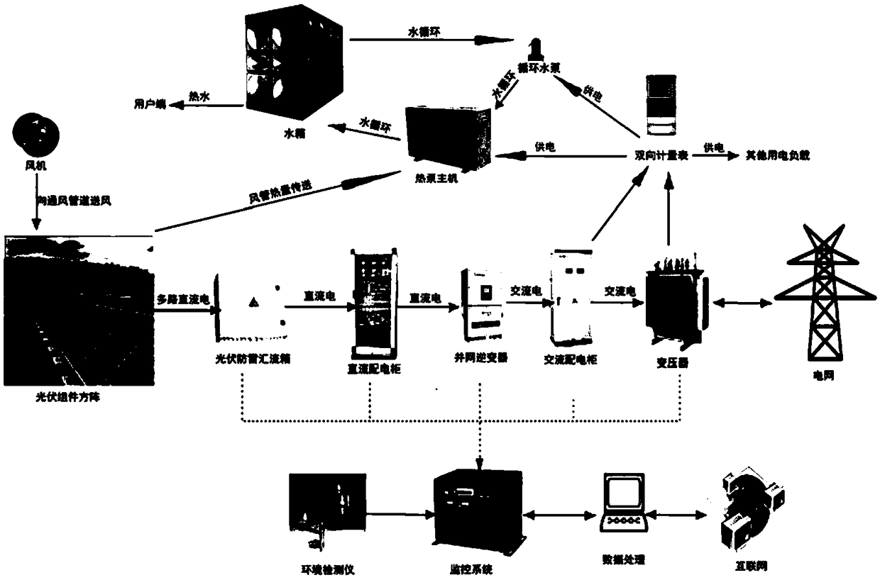
[0038] Such as image 3 As shown, the difference between this embodiment and Embodiment 1 is that the photovoltaic module 1 generates electricity through a parallel photovoltaic grid-connected inverter to supply power to the air source heat pump 8 and the circulating water pump 9, and the remaining electricity is used for grid connection, which is effective Realize combined heat and power supply.

[0039] The total power of the air source system of this experimental model is only 2KW, which can be supplied by the photovoltaic power generation system itself and the surplus electricity can be used for the grid.


PUM


Abstract

The invention discloses a solar heat and power combined supply system. By the aid of the solar heat and power combined supply system, the problems of low power generation efficiency of existing photovoltaic modules, low heat transfer efficiency of heat transfer media of heat collection structures in heat transfer procedures and incapability of efficiently utilizing heat and power can be solved. The solar heat and power combined supply system comprises a photovoltaic module, heat collection panels, a constant-temperature water tank and a support frame. The photovoltaic module and the heat collection panels are mounted on the support frame, the heat collection panels are connected with a heat conduction border of the photovoltaic module, a hollow heat exchange space is formed by the heat collection panels, the heat conduction border and the back surface of the photovoltaic module in an enclosed manner, a ventilating pipeline is connected to the back surfaces of the heat collection panelsand is communicated with the heat exchange space, an air blower is mounted at an air inlet of the ventilating pipeline, and an air-source heat pump is arranged at an air outlet of the ventilating pipeline and is connected with the constant-temperature water tank. The solar heat and power combined supply system has the advantages of high power generation efficiency, heat exchange efficiency and heat and power utilization rate, fast heat collection and the like.

Description

Technical field [0001] The invention relates to the field of photovoltaic technology, in particular to a solar energy combined heat and power system. Background technique [0002] Single solar cells cannot be used directly as power sources. As a power source, several single cells must be connected in series, in parallel and tightly sealed into photovoltaic modules. Photovoltaic modules (also called solar panels) are the core component of the solar power generation system and the most important part of the solar power generation system. Its function is to convert solar energy into electric energy, and send it to the storage battery for storage or drive the load to work. [0003] At present, there are two main ways to apply solar energy, one is photovoltaic power generation, and the other is solar thermal utilization. The efficiency of photovoltaic power generation is relatively low, only about 20%, and most of the remaining energy exists in the form of thermal energy. The high-t...

Claims


Application Information

Patent Timeline
Patent Type & Authority Applications(China)
IPC IPC(8): F24S20/40H02S40/44
CPCH02S40/44Y02E10/50Y02E10/60
Inventor 陈骏
Owner SICHUAN SHUANGLV TECH CO LTD
Features
  • Generate Ideas
  • Intellectual Property
  • Life Sciences
  • Materials
  • Tech Scout
  • Unparalleled Data Quality
  • Higher Quality Content
  • 60% Fewer Hallucinations
Learn More