Degassing tank for lubricating grease

A degassing tank and grease technology, applied in lubricating compositions, foam dispersion/prevention, non-rotational vibration suppression, etc., can solve the problem of inability to centrifugally remove bubbles, achieve good molding effect, improve service life, and reduce vibration wear effect

Inactive Publication Date: 2018-11-06
东营市鑫泰来工贸有限公司
View PDF1 Cites 0 Cited by
  • Summary
  • Abstract
  • Description
  • Claims
  • Application Information

AI Technical Summary

Problems solved by technology

[0004] Aiming at the deficiencies of the prior art, the present invention provides a degassing tank for lubricating grease, which solves the problem that the current degassing tank for lubricating grease cannot centrifugally remove air bubbles, etc.

Method used


Image

  • Degassing tank for lubricating grease
  • Degassing tank for lubricating grease

Examples


Embodiment Construction

[0016] The following will clearly and completely describe the technical solutions in the embodiments of the present invention with reference to the accompanying drawings in the embodiments of the present invention. Obviously, the described embodiments are only some, not all, embodiments of the present invention. Based on the embodiments of the present invention, all other embodiments obtained by persons of ordinary skill in the art without making creative efforts belong to the protection scope of the present invention.

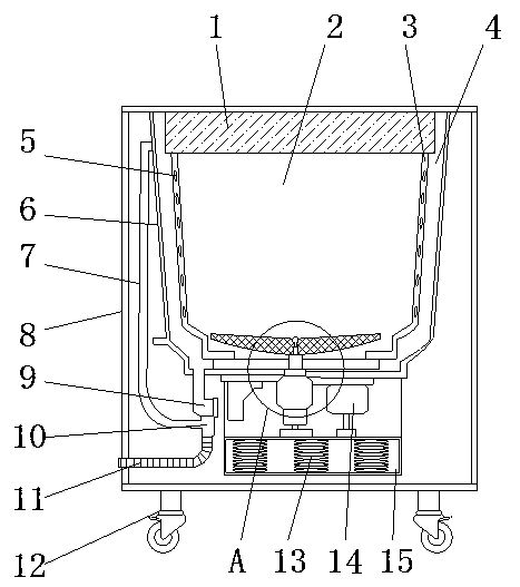
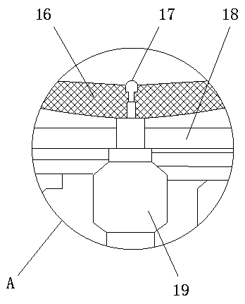
[0017] Such as Figure 1-2 As shown, the present invention provides a technical solution: a degassing tank for lubricating grease, including a body 8, a dehydration bucket 2 is arranged inside the body 8, and a cylinder wall 3 is arranged on the outside of the dehydration bucket 2, and the surface of the cylinder wall 3 is arranged There is a slot 5, and the outer side of the dehydration bucket 2 is wrapped with a water bucket 4, and both sides of the water bu...


PUM


Abstract

The invention discloses a degassing tank for lubricating grease. The degassing tank comprises a machine body, wherein the machine body is internally provided with a dehydration bucket; groove holes are formed in the surface of a cylinder wall; the outer side of the dehydration bucket is wrapped by a water containing bucket; baffle plates are arranged on both sides of the water containing bucket; one end of the water containing bucket is connected with a three-way valve through an overflowing tube; a water drainage tube is mounted at one end of the three-way valve; a water drainage electromagnetic valve is arranged inside the water drainage tube; an electromotor is mounted at the bottom of the dehydration bucket; a speed reduction clutch is arranged on one side of the electromotor; the electromotor is connected with an aluminum alloy disc through a rotating shaft; the upper part of the aluminum alloy disc is rotationally connected with an impeller through an impeller shaft; damping cabins are formed in bottoms of both the speed reduction clutch and the electromotor; damping springs are mounted inside the damping cabins. Due to adoption of the dehydration bucket, the water containingbucket, the three-way valve, the electromotor and the damping springs, the problems that bubbles cannot be centrifuged to be eliminated by a conventional degassing tank for lubricating grease, and the like, can be solved.

Description

technical field [0001] The invention relates to the technical field of chemical production equipment, in particular to a degassing tank for lubricating grease. Background technique [0002] Greases are thick, greasy semi-solids. It is used in the friction part of the machine to lubricate and seal. It is also used on metal surfaces to fill voids and prevent rust. It is mainly prepared from mineral oil (or synthetic lubricating oil) and thickener. According to the thickener, it can be divided into two types: soap-based grease and non-soap-based grease. Lithium, sodium, calcium, aluminum, zinc and other metal soaps are commonly used as thickeners for soap base fats, as well as potassium, barium, lead, manganese and other metal soaps. Graphite, carbon black, asbestos and synthetic (such as polyurea base, bentonite) are used as the thickener of non-soap base grease. According to the application, it can be divided into two types: general grease and special grease. The former i...

Claims


Application Information

Patent Timeline
Patent Type & Authority Applications(China)
IPC IPC(8): B01D19/02F16F15/04C10M177/00
CPCB01D19/02F16F15/04C10M177/00
Inventor 王庆华张争辉刘爱红
Owner 东营市鑫泰来工贸有限公司
Why Eureka
Try Eureka