Energy-saving in-situ thermal desorption treatment device and energy-saving in-situ thermal desorption treatment method for greasy dirty contaminated soil

A technology of polluted soil and treatment equipment, which is applied in the field of energy-saving in-situ thermal desorption treatment equipment, which can solve the problems of secondary pollution, increased construction costs, and large hardened area of ​​equipment, and achieves easy operation, simple device composition, and low operating costs Effect

Inactive Publication Date: 2018-11-06
新疆维吾尔自治区固体废物管理中心
View PDF19 Cites 14 Cited by
  • Summary
  • Abstract
  • Description
  • Claims
  • Application Information

AI Technical Summary

Problems solved by technology

Common indirect thermal desorption technologies are mainly operated in ectopic excavation and transshipment. The hardening area of ​​the equipment is large,

Method used


Image

  • Energy-saving in-situ thermal desorption treatment device and energy-saving in-situ thermal desorption treatment method for greasy dirty contaminated soil
  • Energy-saving in-situ thermal desorption treatment device and energy-saving in-situ thermal desorption treatment method for greasy dirty contaminated soil

Examples


Embodiment 1

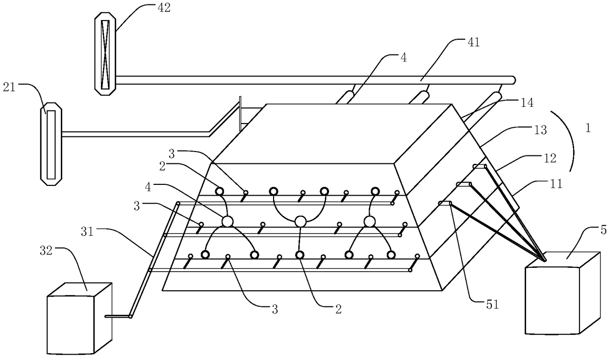
[0058] The schematic diagram of the composition and structure of the energy-saving in-situ thermal desorption treatment device disclosed in Example 1 is as follows figure 1 In the examples described, the structures in the figures are not drawn strictly to scale in order to highlight the characteristics of different parts and assemblies.

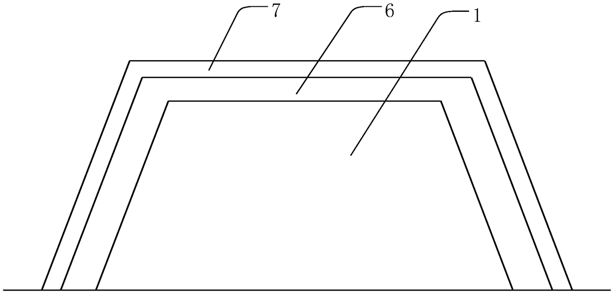
[0059] Contaminated soil after excavation is built into a quadrangular platform-shaped soil mound 1 in situ. The soil mound 1 includes four layers of contaminated soil, laid in sequence from bottom to top, and the height of each layer of contaminated soil is between 0.6 and 1m; After laying the first layer of polluted soil 11 on the bottom layer, install the heating pipe 2 and the extraction pipe 3. There are multiple heating pipes 2 and multiple extraction pipes 3. The distance between the lifting tube 3 and the heating tube 2 is set between 30 and 50 cm; the extraction tube 3 is cut and processed; a temperature sensor (not shown in the figu...


PUM


Abstract

The invention discloses an energy-saving in-situ thermal desorption treatment device and an energy-saving in-situ thermal desorption treatment method for greasy dirty contaminated soil. The energy-saving in-situ thermal desorption treatment device comprises a heating assembly, an extraction assembly, a smoke emission assembly, an inert gas blowing-in assembly, a monitoring assembly and a contaminated gas treatment assembly; the heating assembly comprises heating pipes; the heating pipes are arranged in the greasy dirty contaminated soil; the extraction assembly comprises extraction tubes; theextraction tubes are arranged in the greasy dirty contaminated soil; the flue gas emission assembly comprises smoke return pipes; the smoke return pipes communicate with the heating pipes; the monitoring assembly is arranged in the greasy dirty contaminated soil; and the contaminated gas treatment assembly communicates with the extraction assembly. The energy-saving in-situ thermal desorption treatment method comprises the steps that a greasy dirty contaminated soil hillock is established in a different place on the spot; in the process of establishing the greasy dirty contaminated soil hillock, the energy-saving in-situ thermal desorption treatment device for the greasy dirty contaminated soil disclosed by the invention is arranged; a thermal insulation layer and a sealing layer are sequentially arranged outside the established hillock; and the hillock is heated, and volatile components of greasy dirt in the soil after being heated enter the contaminated gas treatment assembly via theextraction assembly, so that greasy dirt recovery is achieved.

Description

technical field [0001] The invention belongs to the technical field of environmental protection, and in particular relates to an energy-saving in-situ thermal desorption treatment device and treatment method for oil polluted soil. Background technique [0002] The pollution of petroleum hydrocarbons to soil has different characteristics from other soil pollution, mainly manifested in the penetration of the soil surface. Petroleum hydrocarbons often fill almost all the pores in the soil on a certain area and at a certain depth, blocking most of the soil. At the same time, due to the viscosity of petroleum hydrocarbons, the originally scattered soil particles in the soil are glued together, changing the original structural characteristics of the soil. Petroleum hydrocarbon components are often very complex, and this complexity is intertwined with the complexity of the contaminated soil structure. Therefore, the treatment of petroleum hydrocarbon-contaminated soil puts forward ...

Claims


Application Information

Patent Timeline
IPC IPC(8): B09C1/06
CPCB09C1/06B09C2101/00
Inventor 李新琪殷小炜孟园白杰刘亮亮
Owner 新疆维吾尔自治区固体废物管理中心
Why Eureka
Try Eureka