
mql oil mist terminal mixing system

A mixing system and oil mist technology, applied in the direction of mixers, mixing methods, manufacturing tools, etc., can solve the problems of oil mist reduction, large oil mist particles, control lag, etc., and achieve simple structure, small volume, and solve control lag Effect

Active Publication Date: 2019-11-08
DG ARMORINE ENERGY EFFICIENT & ECO FRIENDLY TECH
View PDF4 Cites 0 Cited by
  • Summary
  • Abstract
  • Description
  • Claims
  • Application Information

AI Technical Summary

Problems solved by technology

However, the oil mist particles generated by the oil mist generating device of the Venturi atomizer are relatively large and cannot reach the um level. The oil mist particles collide and fuse with each other in such a long pipeline, making the oil mist particles bigger and bigger, and finally a large part Turn into small oil droplets, some of them will stick to the pipe wall, and the other part will stick to the inner channel wall of the main shaft due to the centrifugal force generated by the high-speed rotating spindle channel during processing. The greater the impact, the less oil mist that can actually be sent to the tool processing area
Therefore, even if there is an adjustable oil mist thickening device on the host side to increase the amount of oil mist, it will still be useless or ineffective after these problems are gradually differentiated, and there is a problem of control lag
Therefore, it is necessary to provide a new MQL oil mist terminal mixing system to overcome the above technical defects

Method used


Image

  • mql oil mist terminal mixing system

Examples


Embodiment Construction

[0015] In order to describe the technical content, structural features, and achieved effects of the present invention in detail, the following will be described in detail in conjunction with the embodiments and accompanying drawings.

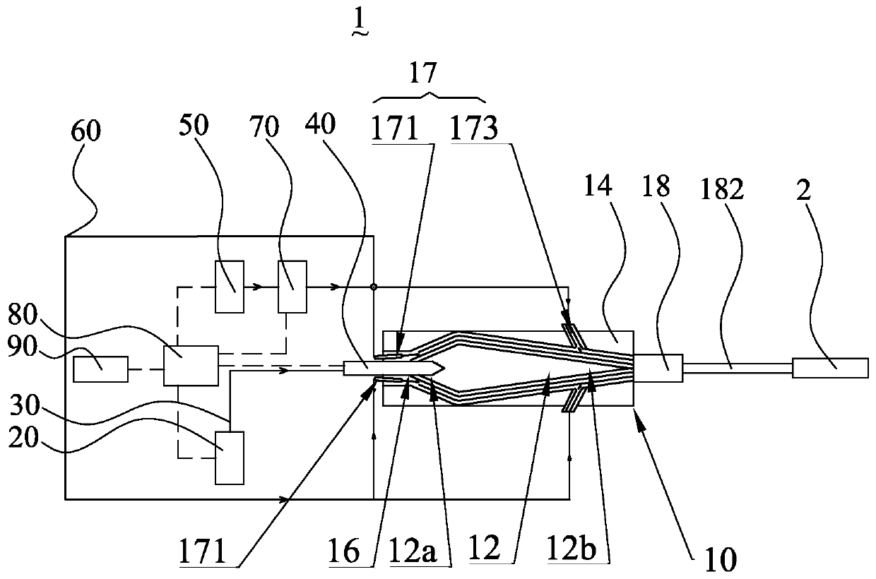
[0016] Such as figure 1 As shown, the MQL oil mist terminal mixing system 1 of the present invention includes an oil-gas mixing chamber 10, an oil booster 20, at least one first delivery pipe 30, at least one first control valve 40, an air booster 50, and at least one second The delivery pipe 60 , at least one second control valve 70 and the PLC control system 80 .

[0017] Specifically, the oil-gas mixing chamber 10 is generally made of metal and has an inner chamber 12 and a chamber wall 14. The inner chamber 12 is shuttle-shaped and has a front end 12a and a rear end 12b. The rear end 12b is narrower than the front end 12a. The wall 14 defines at least one first inlet 16 , at least one second inlet 17 and at least one outlet 18 . In this em...


PUM


Abstract

The invention discloses an MQL oil mist terminal mixing system, comprising an oil-gas mixing chamber, an oil booster device, a gas booster device, at least one first and second delivery pipe, at least one first and second control valves; an oil-gas mixing chamber It has at least one first, second inlet and at least one outlet; the oil pressurization device pressurizes the cutting oil; at least one first delivery pipe delivers the pressurized cutting oil to the oil-gas mixing chamber through at least one first inlet ; At least one first control valve is arranged on at least one first delivery pipe to control the delivery volume of cutting oil; the gas booster device pressurizes the gas; The compressed gas is sent to the oil-gas mixing chamber; at least one second control valve is arranged on at least one second delivery pipe to control the delivery amount of the gas, wherein the pressurized cutting oil and gas are in the oil-gas mixing chamber The oil mist is mixed to form oil mist, and the oil mist is effectively and controllably transported to the main shaft passage through at least one outlet.

Description

technical field [0001] The invention relates to a tool micro-lubrication system of a machining center, in particular to an MQL oil mist terminal mixing system capable of generating small-diameter oil mist particles and effectively and controllably transporting the oil mist to a cutting processing area. Background technique [0002] High-speed cutting is a high-performance process technology that has been widely used in aviation, mold, automobile and other industries. The ability of the cutting fluid to penetrate into the processing area is the key to measure the lubrication and cooling. In the traditional processing process, the high-speed rotation of the machine tool spindle produces huge centrifugal force and high-speed flow field. It is difficult for most of the cutting fluid to enter under the traditional pouring cooling method. In the cutting area, it is difficult to achieve effective cooling of the processing area; especially when processing difficult-to-machine materi...

Claims


Application Information

Patent Timeline
Patent Type & Authority Patents(China)
IPC IPC(8): B23Q11/10B01F3/04B01F15/02
CPCB23Q11/10B01F23/213B01F23/21321B01F35/71745B01F35/7179B01F2101/39Y02P70/10
Inventor 熊伟强姚永权张世德
Owner DG ARMORINE ENERGY EFFICIENT & ECO FRIENDLY TECH
Learn More