A method for in situ nondestructive exfoliation of quantum dots

A quantum dot and in-situ technology, which is applied in the field of in-situ non-destructive peeling of quantum dots, can solve the problems of material damage, uneconomical, pollution, etc., and achieve the effects of low cost, wide applicability, and reducing the impact of anisotropy

Active Publication Date: 2020-09-08
SUZHOU UNIV
View PDF1 Cites 0 Cited by
  • Summary
  • Abstract
  • Description
  • Claims
  • Application Information

AI Technical Summary

Problems solved by technology

[0008] In order to solve the above-mentioned technical problems, the object of the present invention is to provide a method for in-situ non-destructive exfoliation of quantum dots. The method of the present invention can effectively avoid oxidation, pollution, material damage, time-consuming and uneconomical problems in the current mainstream exfoliation methods. question

Method used


Image

  • A method for in situ nondestructive exfoliation of quantum dots
  • A method for in situ nondestructive exfoliation of quantum dots
  • A method for in situ nondestructive exfoliation of quantum dots

Examples


Embodiment 1

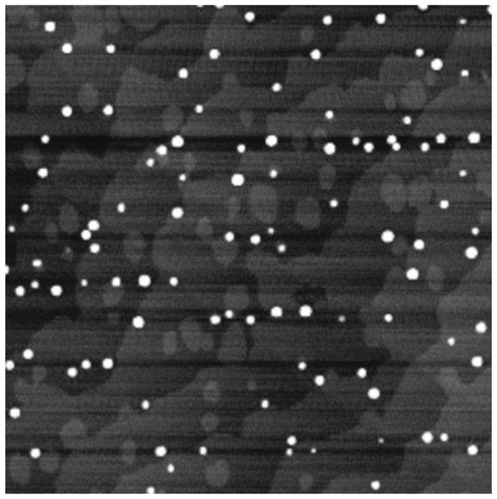
[0034] The sample of InAs / GaAs quantum dots to be stripped (that is, the InAs quantum dots are distributed on the surface of the substrate formed by the GaAs film) is heated to the critical desorption temperature of InAs under the premise of an As-rich atmosphere in the MBE growth chamber. In this embodiment, the arsenic pressure is set to 8.0×10 -7 Torr, the critical desorption temperature is 525°C. Such as image 3 As shown, the AFM test results of the quantum dot sample to be stripped indicate that a certain density of InAs quantum dots (white dots) have been successfully grown on the surface of the GaAs substrate.

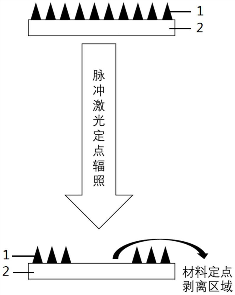
[0035] Then a single pulse laser was introduced to irradiate the sample surface, where the laser wavelength was 355nm, the pulse width was 10ns, and the laser energy was 10mJ. The sample surface after laser irradiation is like Figure 4 As shown, I can see that the InAs quantum dots have been stripped clean (the white dots have disappeared), leaving only the flat...

Embodiment 2

[0039] The InAs quantum dots in the InAs / GaAs quantum dot samples were stripped according to the method of Example 1, the difference is that the arsenic pressure is set to 8.0×10 -6 Torr, the critical desorption temperature is 510℃, and the laser energy of the single pulse laser is 15mJ.

Embodiment 3

[0041] The InAs quantum dots in the InAs / GaAs quantum dot samples were stripped according to the method of Example 1, the difference is that the arsenic pressure is set to 8.0×10 -7 Torr, the critical desorption temperature is 530°C, and the laser energy of the single pulse laser is 20mJ.

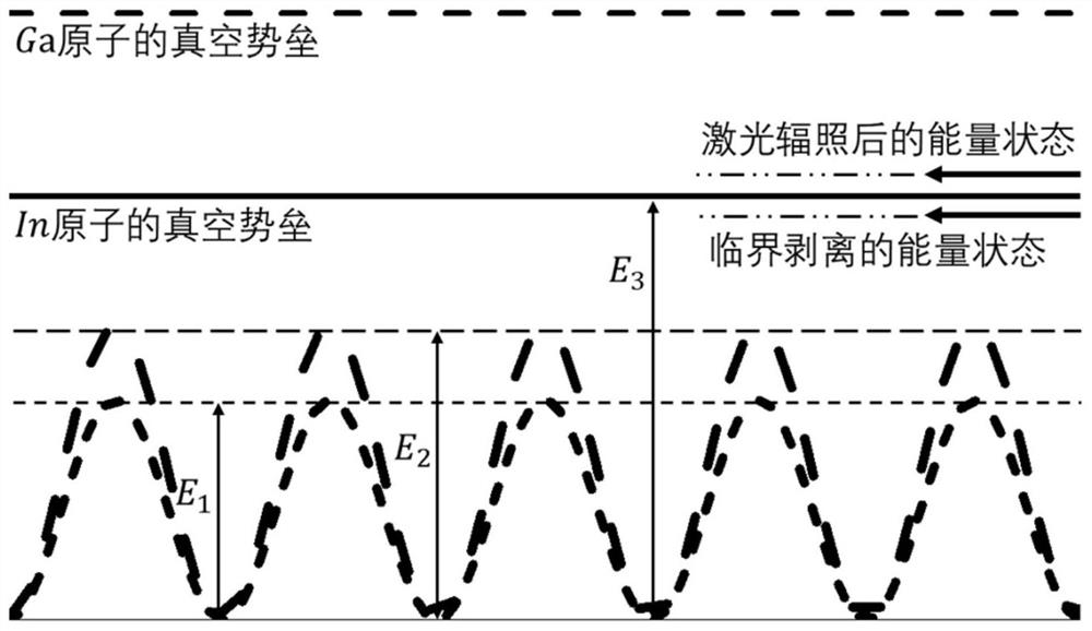
[0042] In addition, according to the above method, you can also choose different quantum dot systems, such as InSb / AlSb quantum dots, InSb / GaSb quantum dots, InSb / AlAs quantum dots, InSb / GaAs quantum dots, InN / AlN quantum dots or InN / GaN quantum dots Dot system, the one before " / " is the quantum dot, and the one after " / " is the substrate material. In the quantum dot system, the quantum dots with lower vacuum energy barrier and lower bonding energy are stripped, and the specific critical desorption temperature is The settings and selection of pulse laser parameters are set according to the energy of the quantum dots to be stripped.


PUM

PropertyMeasurementUnit
wavelengthaaaaaaaaaa

Abstract

The invention relates to a method for in situ non-destructive stripping of quantum dots. The method comprises the following steps: heating a substrate having quantum dots on the surface thereof to thecritical desorption temperature of quantum dots, wherein the quantum dots are III-V group quantum dots, the material of the substrate is a III-V compound, and the bond energy of the quantum dots is lower than the bond energy of the compound in the substrate; then applying pulse laser to the quantum dots, so that the atoms in the quantum dots are excited and detached in situ from the surface of the substrate. The method provided by the invention can effectively avoid the problems of oxidation, pollution, material destruction, time consuming and diseconomy existing in current mainstream stripping methods.

Description

Technical field [0001] The present invention relates to the technical field of quantum dot stripping, in particular to a method for in-situ non-destructive stripping of quantum dots. Background technique [0002] The growth of quantum dots is mainly based on molecular beam epitaxy (MBE) technology. The controllability of molecular beam epitaxy technology plays an extremely important role in promoting the development of quantum dots. Stripping off quantum dots during the experiment is an important step in the controllable measures of molecular beam epitaxy. [0003] In the early days of molecular beam epitaxy, scientists often used elevated substrate temperature to perform thermal evaporation from the surface of the substrate to achieve the peeling of quantum dots. This method can achieve large-area peeling and is simple to operate. However, it is worth noting that high-temperature peeling cannot precisely control the peeling area, which limits the application of this technology. ...

Claims


Application Information

Patent Timeline
Patent Type & Authority Patents(China)
IPC IPC(8): C01G28/00C01G30/00C01B21/06B82Y30/00B82Y40/00
CPCB82Y30/00B82Y40/00C01B21/0632C01G28/00C01G30/00
Inventor 石震武缪力力杨琳韵杨新宁彭长四
Owner SUZHOU UNIV
Why Eureka
Try Eureka