Non-interference and high-stability ribbon loom weft insertion device

A high-stability, weft-inserting device technology, used in textiles, textiles, papermaking, shuttles, etc., can solve the problems of insufficient stability, poor product quality, imperfect structure, etc., and achieve improved webbing quality and device life. Simple structure , routing and corresponding structural design optimization effect

Pending Publication Date: 2018-11-06
HUZHOU HYUNDAI TEXTILE MACHINERY
View PDF8 Cites 0 Cited by
  • Summary
  • Abstract
  • Description
  • Claims
  • Application Information

AI Technical Summary

Problems solved by technology

[0003] The technical purpose of the present invention is to provide a non-interference and high-stability weft insertion device for a loom, which solves the problems of imperfect structure, insufficient stability, and poor quality of products obtained in the traditional weft insertion device for a loom

Method used


Image

  • Non-interference and high-stability ribbon loom weft insertion device
  • Non-interference and high-stability ribbon loom weft insertion device
  • Non-interference and high-stability ribbon loom weft insertion device

Examples


Embodiment 1

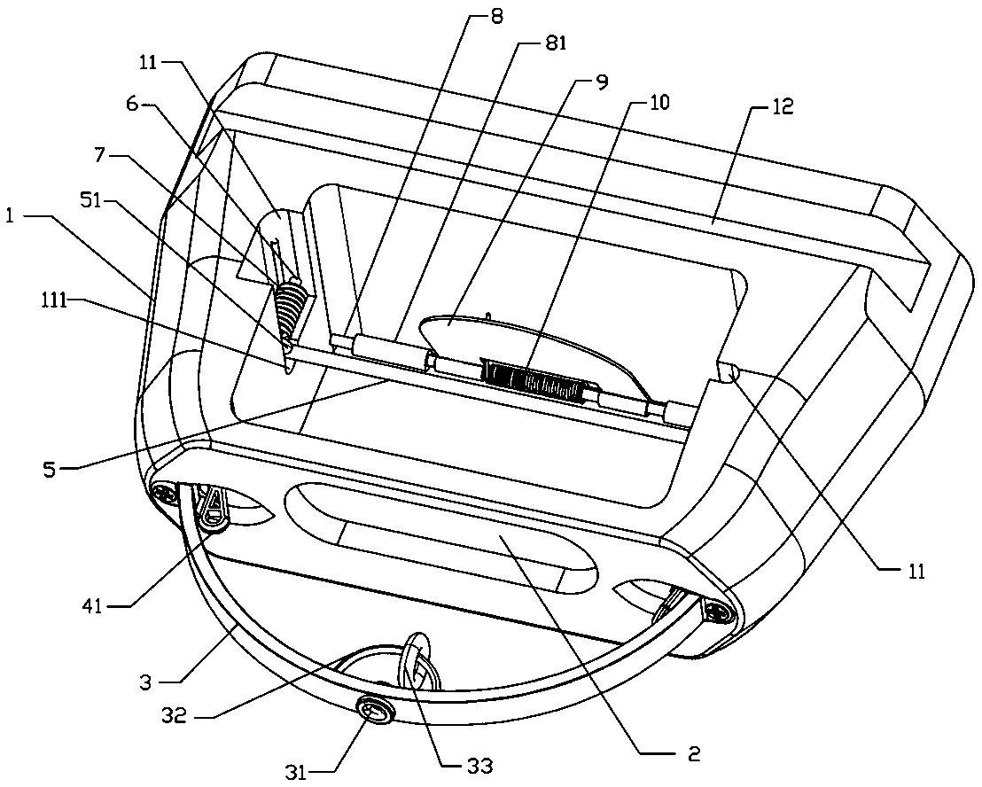
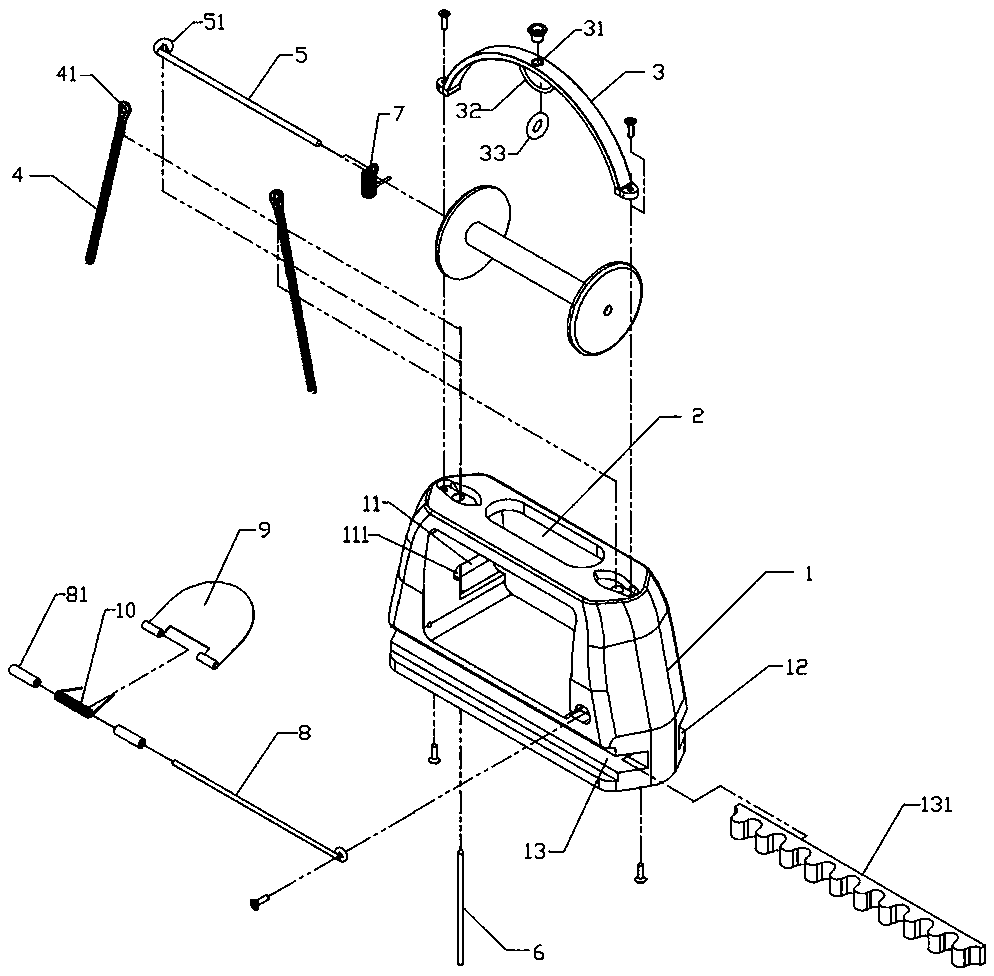
[0035] Embodiment one: see figure 1 , figure 2 , a weft insertion device for a loom without interference and high stability, including a shuttle body 1, the upper surface of the rear end of the shuttle body 1 is provided with an upper guide part 12 for wooden foot connection (there will be wooden foot components on the shuttle box, usually divided into The structure of the upper wooden leg and the lower wooden leg, the upper wooden leg is generally provided with a guide strip, and the lower wooden leg is provided with a guide wheel, and the whole is relatively slidingly connected with the shuttle body 1), and the upper wooden leg is connected with the upper guide part 12 includes the upper guide groove. Of course, there is no guide bar on the wooden foot but a guide groove is provided. Then the upper guide part 12 for wooden foot connection can be changed to an upper guide strip accordingly. The diagram only shows the way of the upper guide groove The lower surface of the sh...

Embodiment 2

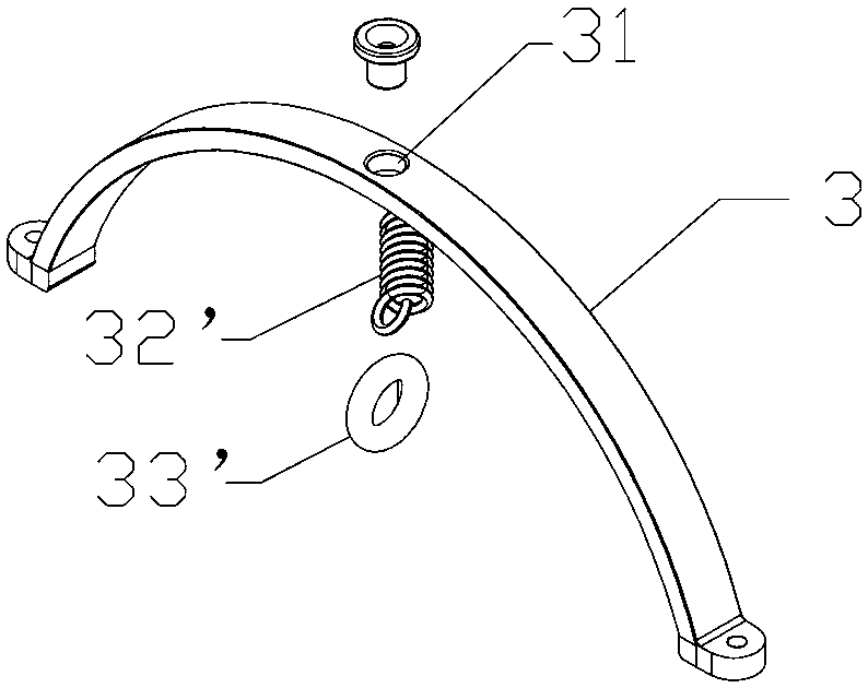
[0040] Embodiment two: see image 3 The difference between this embodiment and Embodiment 1 is that the follow-up mechanism includes an elastic member 32' connected to the inner wall of the support frame 3 itself on the side of the weft thread passing space and a weft threading ring 33 connected to the end of the elastic member 32' ', is another implementation of the follow-up mechanism.

Embodiment 3

[0041] Embodiment three: see Figure 4 The difference between this embodiment and Embodiment 1 is that the follow-up mechanism includes a swing rod 32'' hinged to the inner wall of the support frame 3 itself on the side of the weft thread passing space and a weft passing rod connected to the end of the swing rod 32''. The ring 33'' is another implementation of the follow-up mechanism.

[0042] See Figure 5 (The thicker line is the weft thread). The weft thread lead-out component and the weft thread pull-back component cooperate with each other to complete the weft insertion. The weft thread has a corresponding threading method in this technical solution: the weft thread comes out from the weft thread path, and first passes through the weft thread. Move the weft threading ring 33, then pass the thread passing head 41 on one side, then pass the thread passing head 41 on the other side, and finally pass the weft outlet 31. In the actual working process, the entire shuttle body...


PUM


Abstract

The invention provides a non-interference and high-stability ribbon loom weft insertion device. The non-interference and high-stability ribbon loom weft insertion device comprises a shuttle body, andfurther comprises a weft yarn leading-out assembly connected to the shuttle body and a weft yarn pulling-back assembly which is matched with the weft yarn leading-out assembly to commonly lead yarn movement; the shuttle body is internally provided with two mounting channels; at least one mounting channel is arranged at each of two sides of the shuttle body; the weft yarn pulling-back assembly is arranged in the mounting channels; a mounting cavity is mounted in the shuttle body; the mounting cavity is internally and detachably provided with a quill fixing assembly; a communicated weft yarn passing path is arranged between the mounting cavity and the weft yarn leading-out assembly. The non-interference and high-stability ribbon loom weft insertion device provided by the invention is simplein structure and convenient to use; the assemblies are relatively easy and convenient to dismount and adjust; yarn movement and a corresponding structure design are optimized and the device is easy toproduce and manufacture; in a movement process of weft yarns, interference does not easily occur and the movement is smooth; friction abrasion is not easy to occur and the quality of ribbons and theservice life of the device are effectively improved.

Description

technical field [0001] The invention relates to the technical field of textile machinery, in particular to a weft insertion device of a loom with no interference and high stability. Background technique [0002] Ribbon loom is a machine that can weave ribbons of various widths, suitable for weaving various round or flat non-elastic and elastic ropes, mainly weaving various ropes, shoelaces, elastic belts, decorative belts, high tension belts, fishnet lines , fishing line, tow rope, marine rope, sports belt, curtain belt, wire, fiber and other high-quality products. According to different weaving methods, it can be divided into two categories: shuttle loom and weaving machine. Shuttle looms are divided into two categories: shuttleless looms and shuttle looms. Although the shuttle loom has fewer uses than the shuttleless loom, it still has a relatively large installed capacity in the industry. The structure of the traditional shuttle loom lacks innovation, and its shuttle s...

Claims


Application Information

Patent Timeline
Patent Type & Authority Applications(China)
IPC IPC(8): D03J5/02D03J5/08
CPCD03J5/02D03J5/08
Inventor 韦文泉孙立新
Owner HUZHOU HYUNDAI TEXTILE MACHINERY
Why Eureka
Try Eureka