
Eureka
For R&D, Eureka makes reading and utilizing patents & technical documents easy.
Eureka AIR
Designed for self-driven R&D workflows. Generate viable solutions, solve complex R&D challenges, empower your innovation with AI.

Eureka Materials
Designed for material experts only. Revolutionize your material R&D, from search, analyze, to developing new materials.

TechResearch
Generate reliable direction feasibility study reports for your R&D in just a few steps.

TechSeek
Discover and master advanced knowledge NOW. Basics, ideas, possibilities, all at once.

TechMind
As an expert in R&D Theories, TechMind can generates customized viable solutions instantly.

TechRisk
Analyze your overall solution with one click, know your potential R&D risks in advance.

TechMonitor
Get weekly tech updates, stay abreast of the latest tech innovations and key insights.
Vertical centrifugal pump with air dynamic pressure bearings
An air dynamic pressure bearing and vertical centrifugal technology, which is applied to non-variable pumps, parts of pumping devices for elastic fluids, pumps, etc., can solve the difficulty of vertical centrifugal pump maintenance and oil level control Narrow range, bearing wear and other problems, to achieve the effect of low power consumption, reduced maintenance, and long life
- Summary
- Abstract
- Description
- Claims
- Application Information
AI Technical Summary
Problems solved by technology
Method used
Image

Examples
Embodiment 1
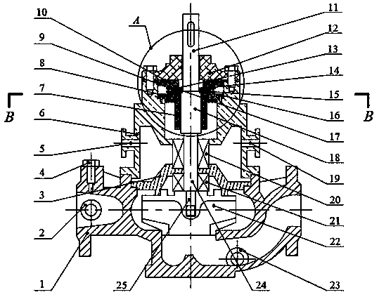
[0027] Such as Figure 1-4 As shown, a vertical centrifugal pump configured with an air dynamic pressure bearing includes a pump casing, an impeller 22, a mechanical seal, a shaft, and an air dynamic pressure bearing; wherein, the air dynamic pressure bearing includes an air dynamic pressure radial bearing 7 and two sets of Aerodynamic thrust bearings (the upper thrust bearing 13 and the lower thrust bearing 16, the two sets of aerodynamic thrust bearings have the same structure);
[0028] The pump casing includes a pump body 1, a pump cover 3, a bearing housing 6 and a bearing gland 12, the pump cover 3 is located in the bearing housing 6, the pump body 1 and the pump cover 3, the pump body 1 and the bearing housing 6, and the bearing housing 6 It is respectively connected with the bearing gland 12 by bolts; one side of the pump body 1 is provided with a pressure plug 2 and an exhaust valve 4, the exhaust valve 4 is located at the top of the side wall of the pump body 1, and ...
Embodiment 2
[0031] The structure of this embodiment is substantially the same as that of Embodiment 1, except that the diameters of the four journals are: journal I25journal IV11;
Embodiment 3
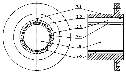
[0033] The structure of this embodiment is basically the same as that of Embodiment 1, except that the aerodynamic radial bearing is an elastic foil aerodynamic radial bearing, which includes a radial bearing top foil 7-5, a radial bearing wave Foil 7-3 and bearing seat 7-2, from outside to inside are the concentric rings formed by bearing seat 7-2, radial bearing wave foil 7-3 and radial bearing top layer foil 7-5, bearing seat 7- 2 is equipped with positioning pin Ⅲ7-1, and the elastic foil air dynamic pressure radial bearing is a full-circle 360° elastic foil air dynamic pressure radial bearing;
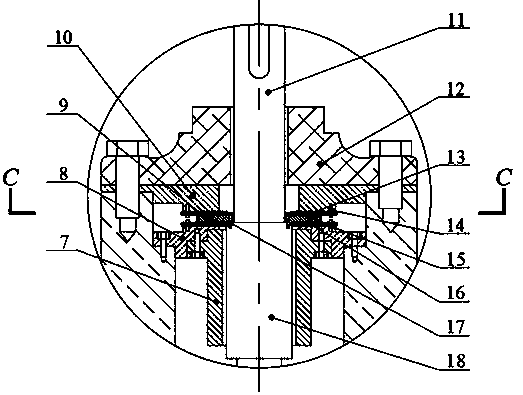
[0034]The aerodynamic pressure thrust bearing is an elastic foil aerodynamic pressure thrust bearing, including a bottom plate 13-2, a thrust bearing wave foil 13-3 and a thrust bearing top layer foil 13-4, and the bottom plate 13-2 is a circle ring shape, the thrust bearing wave foil 13-3 is evenly arranged on the bottom plate 13-2 along the circumferential direction, the thrust ...
PUM
 Abstract
Description
Claims
Application Information
 - R&D Engineer
- R&D Manager
- IP Professional
- Industry Leading Data Capabilities
- Powerful AI technology
- Patent DNA Extraction
Browse by: Latest US Patents, China's latest patents, Technical Efficacy Thesaurus, Application Domain, Technology Topic, Popular Technical Reports.
© 2024 PatSnap. All rights reserved.Legal|Privacy policy|Modern Slavery Act Transparency Statement|Sitemap|About US| Contact US: help@patsnap.com