
Optical fiber coupling-based high-polarization extinction ratio waveguide polarizer and manufacturing method thereof

A polarization extinction ratio and fiber coupling technology, applied in optical waveguides, light guides, optics, etc., can solve the problems of low optical power threshold and high insertion loss, and achieve the effect of improving polarization extinction ratio, low coupling loss and reducing probability.

Pending Publication Date: 2018-11-06
HEILONGJIANG UNIV OF TECH +1
View PDF0 Cites 2 Cited by
  • Summary
  • Abstract
  • Description
  • Claims
  • Application Information

AI Technical Summary

Problems solved by technology

[0006] Aiming at the problems of high insertion loss and low optical power threshold of waveguide polarizers based on lithium niobate annealed proton exchange waveguides, and further improving the polarization extinction ratio of such devices, the present invention proposes a fiber-coupled high polarization Extinction ratio waveguide polarizer and its manufacturing method, by using magnesium oxide-doped lithium niobate crystal or near-stoichiometric ratio lithium niobate crystal to realize the improvement of device optical power threshold, and adopting magnesium oxide-doped lithium niobate crystal or near-stoichiometric lithium niobate crystal Fabrication of antiproton exchange optical waveguides in stoichiometric lithium niobate crystals to reduce waveguide insertion loss

Method used


Image

  • Optical fiber coupling-based high-polarization extinction ratio waveguide polarizer and manufacturing method thereof
  • Optical fiber coupling-based high-polarization extinction ratio waveguide polarizer and manufacturing method thereof
  • Optical fiber coupling-based high-polarization extinction ratio waveguide polarizer and manufacturing method thereof

Examples


Embodiment Construction

[0033] The present invention will be described in further detail below in conjunction with the accompanying drawings and specific embodiments. It should be understood that the specific embodiments described here are only used to explain the present invention, not to limit the present invention.

[0034] It should be noted that, in the case of no conflict, the embodiments in the present application and the features in the embodiments can be combined with each other.

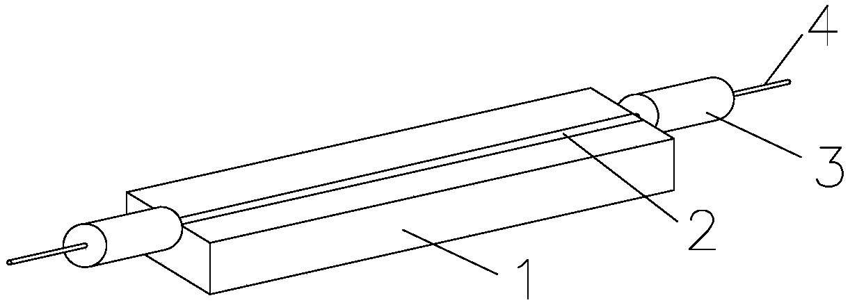
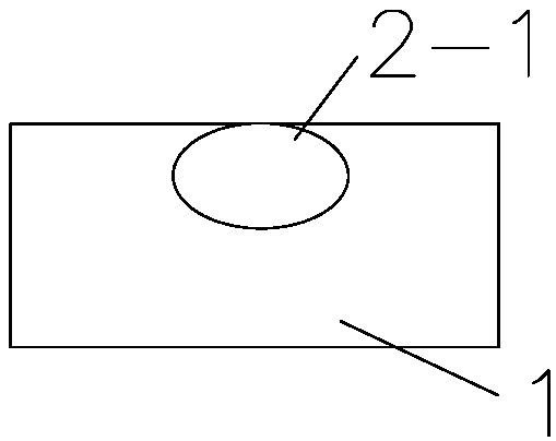
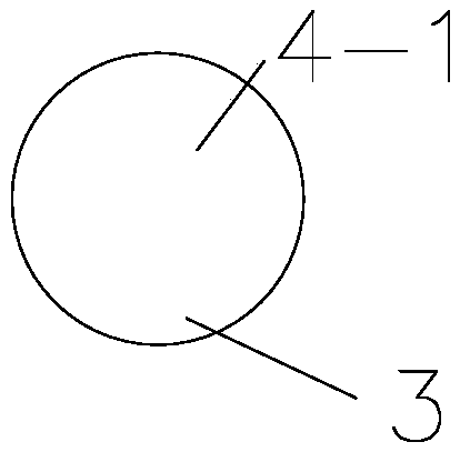
[0035] like Figure 1-Figure 5 As shown, this embodiment provides a fiber-coupled high polarization extinction ratio waveguide polarizer, including: a lithium niobate wafer 5 , an optical waveguide 6 , an optical fiber sleeve 3 , and a polarization-maintaining optical fiber 4 . The lithium niobate wafer 5 is an optical-grade magnesium oxide-doped lithium niobate crystal 5, and the tangential direction of the crystal is X-cut Y-pass or Z-cut Y-pass. In order to ensure sufficient coupling strength between the lith...


PUM

PropertyMeasurementUnit
thicknessaaaaaaaaaa
widthaaaaaaaaaa
thicknessaaaaaaaaaa

Abstract

The invention provides an optical fiber coupling-based high-polarization extinction ratio waveguide polarizer and a manufacturing method thereof. The invention aims to solve the problems of the high insertion loss and low optical power threshold of a lithium niobate annealed proton exchanged waveguide-based waveguide polarizer and further improve the polarization extinction ratio of such kind of devices. According to the optical fiber coupling-based high-polarization extinction ratio waveguide polarizer and the manufacturing method thereof of the invention, a magnesium oxide doped lithium niobate crystal or a near-stoichiometric lithium niobate crystal is adopted, so that the increase of the optical power threshold of the device can be realized; an anti-proton exchanged waveguide is prepared in the magnesium oxide doped lithium niobate crystal or near-stoichiometric lithium niobate crystal, so that the insertion loss of the waveguide is decreased; and the back surface of the magnesiumoxide doped lithium niobate crystal or near-stoichiometric lithium niobate crystal is slotted and is coated with a light absorbing material, so that the polarization extinction ratio of the waveguidepolarizer can be further improved.

Description

technical field [0001] The invention relates to the technical fields of optical fiber sensing, optical fiber communication and quantum communication, in particular to a fiber-coupled high polarization extinction ratio waveguide polarizer and a manufacturing method thereof. Background technique [0002] Polarizers can convert unpolarized beams or low polarization polarized beams into high polarization extinction ratio beams, and are widely used in polarization-dependent loss measurement systems, optical fiber sensing systems, and optical fiber communication systems. At present, the common fiber polarizer has the advantages of low insertion loss (typical value around 0.5dB), low return loss (typical value around 50dB), high optical power (500mW), etc., but its polarization extinction ratio (typical value 30dB) The indicators are still unable to fully meet the requirements of some application fields, especially the applications that require a higher polarization extinction rati...

Claims


Application Information

Patent Timeline
Patent Type & Authority Applications(China)
IPC IPC(8): G02B6/126G02B6/136G02B6/13
CPCG02B6/126G02B6/13G02B6/136G02B2006/12116G02B2006/12042G02B2006/12166
Inventor 史云玲杨旭魏喜雯褚洪波郑毅张凤环李萍
Owner HEILONGJIANG UNIV OF TECH
Learn More