40.5kV switch equipment system

A switchgear and switchgear technology, applied in the field of 40.5kV switchgear system, can solve the problems affecting the effective control of the arc extinguishing chamber, the insulation failure of the insulation rod, and the unreasonable layout of the switchgear, etc., so as to optimize the surrounding electric field and avoid the cabinet. Overheating, not easy to discharge effect

Active Publication Date: 2018-11-06
四川电器集团股份有限公司
View PDF9 Cites 3 Cited by
  • Summary
  • Abstract
  • Description
  • Claims
  • Application Information

AI Technical Summary

Problems solved by technology

[0007] The purpose of the present invention is to overcome the deficiencies of the prior art and provide a 40.5kV switchgear system to solve the problem of unreasonable layout of each switchgear within the limited space in the cabinet, resulting in waste of space, inconvenient installation, and poor insulation effect. question,
[0008] In addition, it solves the problem that the insulation pull rod is easy to fail insulated at the moment when the insulation pull rod is disconnected and closed in the arc extinguishing chamber of the circuit breaker, resulting in safety accidents
[0009] And to solve the problem that although the existing insulating rod has the length adjustment function, when the extension is adjusted by the screw rod, the length cannot be locked, and it is easy to cause the length of the insulating rod to change during use, thereby affecting the effective control of the arc extinguishing chamber

Method used


Image

  • 40.5kV switch equipment system
  • 40.5kV switch equipment system
  • 40.5kV switch equipment system

Examples


Embodiment

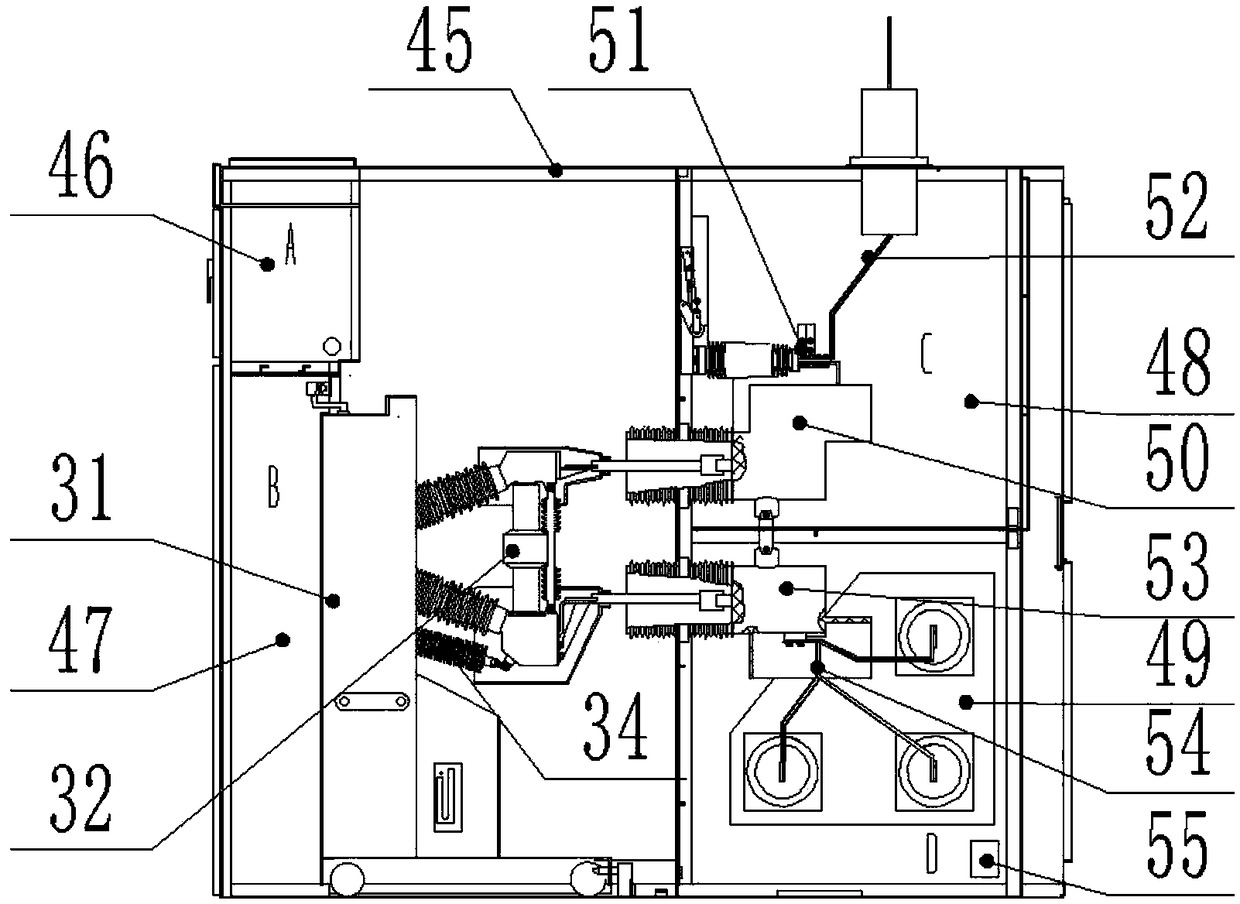
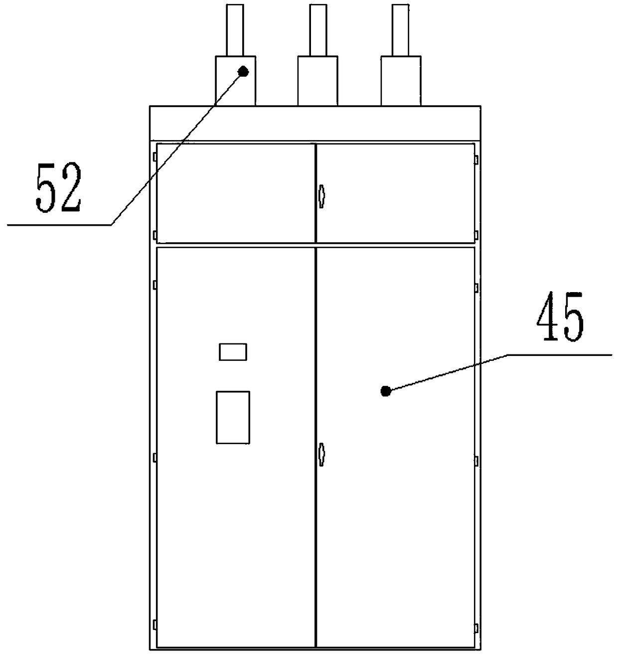
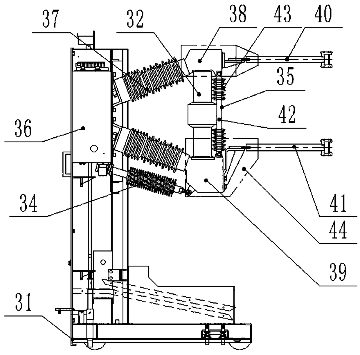
[0046] Such as Figure 1-9 As shown, a 40.5kV switchgear system of the present invention includes a switchgear 45, and the switchgear 45 is divided into an instrument room 46, a handcart room 47, a feeder room 48 and a busbar room 49, and the feeder room 48 is arranged on the busbar Above the handcart room 49, the handcart room 47 is arranged on the left side of the feeder room 48 and the busbar room 49, the instrument room 46 is arranged in the upper left corner of the handcart room 47, and the circuit breaker assembly is arranged in the handcart room 47, so The upper conductive joint 40 on the circuit breaker assembly is connected to the outlet of the upper contact box-type current transformer 50 arranged in the feeder room 48, and the inlet of the upper contact box-type current transformer 50 is connected to the upper branch bus through a grounding switch 51 connector 52; the lower conductive connector 41 on the circuit breaker assembly is connected to the outlet of the low...


PUM


Abstract

The invention discloses a 40.5kV switch equipment system. The system comprises a switch cabinet; an instrument chamber, a handcart chamber, a feeder line chamber and a bus chamber are formed in the switch cabinet; the feeder line chamber is arranged above the bus chamber, the handcart chamber is arranged at the left side of the feeder line chamber and the bus chamber, the instrument chamber is arranged at the left upper corner of the handcart chamber, and a circuit breaker module is arranged in the handcart chamber; an upper conductive connector on the circuit breaker module is connected withan upper contact box type current transformer outlet arranged at the feeder line chamber, the inlet of the upper contact box type current transformer is connected with an upper branch bus connector through a grounding switch; a lower conductive connector on the circuit breaker module is connected with a lower contact box type current transformer outlet arranged at the bus chamber, and the lower contact box type current transformer inlet is connected with a lower branch bus connector; and the circuit breaker module comprises a frame, a vacuum arc extinguish chamber, an operating mechanism, a connecting insulation pull rod and an insulating brace rod.

Description

technical field [0001] The invention relates to the technical field of high-voltage switchgear, in particular to a 40.5kV switchgear system. Background technique [0002] The switchgear cabinet is used to place the switchgear. The mechanical strength of the switchgear cabinet in the prior art is poor, and due to the magnetic circuit that generates a magnetic field when the main bus passes through, the eddy current loss is large, and the safety of the switchgear operation is relatively high. Difference. The 40.5kV switch installed in the plateau environment has higher requirements on the insulation performance of the equipment and requires a more reasonable layout. Wherein the setting position of the current transformer is not reasonable enough, most of the current transformers are arranged on the cabinet in the prior art, but the space in the cabinet is limited, and the loading of the current transformer will compress the space in the cabinet and cause the installation spac...

Claims


Application Information

Patent Timeline
Patent Type & Authority Applications(China)
IPC IPC(8): H02B11/167H02B11/02H02B11/28H02B1/20H01H33/666H01H33/664
CPCH02B1/20H02B11/02H02B11/167H02B11/28H01H33/664H01H33/666
Inventor 唐良雄罗卫东刘叔元代安东梁磊
Owner 四川电器集团股份有限公司
Why Eureka
Try Eureka