
Landfill leachate biochemical effluent treatment reactor and method

A technology of landfill leachate and biochemical effluent, applied in chemical instruments and methods, polluted groundwater/leachate treatment, water/sewage treatment, etc., can solve the problem that COD and TN cannot be removed at the same time, and achieve the effect of relieving pressure

Inactive Publication Date: 2018-11-09
CHINA UNIV OF GEOSCIENCES (BEIJING)
View PDF8 Cites 6 Cited by
  • Summary
  • Abstract
  • Description
  • Claims
  • Application Information

AI Technical Summary

Problems solved by technology

[0008] The purpose of the first aspect of the present invention is to provide a landfill leachate biochemical effluent treatment reactor to solve the technical problem in the prior art that COD and TN cannot be removed simultaneously in the landfill leachate biochemical water

Method used


Image

  • Landfill leachate biochemical effluent treatment reactor and method

Examples


Embodiment 1

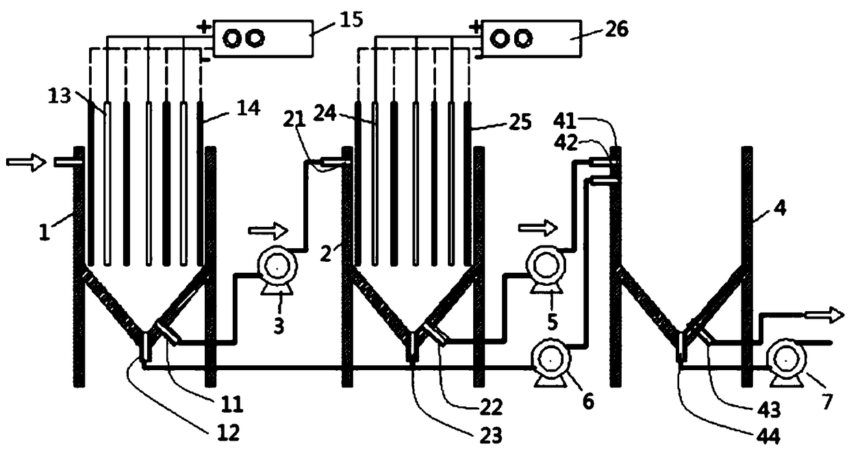
[0076] Such as figure 1 As shown, a landfill leachate biochemical effluent treatment reactor includes: an electrochemical flocculation device 1 , wherein four first cathode plates 14 and three iron anode plates 13 are arranged crosswise in the electrochemical flocculation device 1 . During the operation of the electrochemical flocculation device 1 , the first DC power supply 15 is used for power supply. After the electrochemical flocculation reaction and precipitation, the third pump 6 is turned on to transfer the reducing sludge to the available chlorine elimination device 4 . After the transfer of the reducing sludge is completed, the third pump 6 is turned off, the first pump 3 is turned on, and the electrochemical flocculation effluent is transferred to the electrochemical oxidation device 2 . In the electrochemical oxidation device 2, the second DC power supply 26 is used for power supply. After the electrochemical oxidation reaction precipitation is completed, the second...

Embodiment 2

[0079] The treatment reactor is set up as in Example 1, and the actual landfill leachate biochemical effluent is used as the experimental object, and the current density is set to 50mA / cm during the reaction process 2 , the reaction time in the electrochemical flocculation device 1 is 60min, the reaction time in the electrochemical oxidation device 2 is 120min, the reaction time in the available chlorine elimination device 4 is 10min, and the third solution effluent 43 of the available chlorine elimination device 4 flows out after the reaction BOD in solution 5 The / COD value rose to 0.35 compared to 0.065 of the influent, indicating that the effluent was suitable for further treatment by the microbial reactor. Among them, the COD that can be used by microorganisms is BOD. This is usually the 5-day biochemical oxygen demand, denoted as BOD 5 . BOD 5 / COD is also BOD 5 The proportion in the total COD. The influent is the biochemical aqueous solution entering the electroch...


PUM


Abstract

The invention provides a landfill leachate biochemical effluent treatment reactor and method and relates to the technical field of sewage treatment, aiming at solving the technical problem that COD (Chemical Oxygen Demand) and TN (Total Nitrogen) in landfill leachate biochemical effluent cannot be removed at the same time. The landfill leachate biochemical effluent treatment reactor comprises an electrochemical flocculation device for adsorbing macromolecular difficult-to-degrade organic matters to form reducing sludge and transforming nitrate nitrogen into ammonia nitrogen, an electrochemicaloxidization device for generating effective chlorine and eliminating the effective chlorine to react with the ammonia nitrogen to eliminate the ammonia nitrogen, and a first pump, wherein the electrochemical flocculation device is provided with a first solution outlet and a first sludge outlet; the electrochemical oxidization device is provided with a first solution inlet; an inlet and an outletof the first pump are correspondingly connected and communicated with the first solution outlet and the first solution inlet respectively; the reducing sludge flows out from the first sludge outlet.

Description

technical field [0001] The invention relates to the technical field of sewage treatment, in particular to a biochemical effluent treatment reactor and method for landfill leachate. Background technique [0002] At present, whether in developed or developing countries, municipal solid waste MSW is usually disposed of by landfill because it is an economical and quick method. However, a series of physical, chemical and biological actions of these solid wastes through rainwater leaching and the landfill system itself will produce a high-concentration organic wastewater called landfill leachate. In recent years, scholars at home and abroad have conducted a lot of research on landfill leachate treatment, such as microbial treatment methods, membrane technology and advanced oxidation technology. Among these existing treatment processes, microbial treatment is considered to be the most promising treatment method due to its cost-effectiveness and has been widely promoted. However, ...

Claims


Application Information

Patent Timeline
Patent Type & Authority Applications(China)
IPC IPC(8): C02F1/463C02F1/467C02F101/30C02F103/06
CPCC02F1/463C02F1/4674C02F2101/30C02F2103/06
Inventor 冯传平邓阳陈男
Owner CHINA UNIV OF GEOSCIENCES (BEIJING)
Learn More