
CAN bus-based motor bench experiment device and load control method

A CAN bus, bench experiment technology, applied in the direction of motor generator testing, improvement of basic electrical components, etc., can solve the problem that magnetic powder cannot transmit torque, and achieve the effect of simple structure, rich content, and improved flexibility

Inactive Publication Date: 2018-11-09
HARBIN UNIV OF SCI & TECH
View PDF8 Cites 4 Cited by
  • Summary
  • Abstract
  • Description
  • Claims
  • Application Information

AI Technical Summary

Problems solved by technology

[0003] With the further improvement of motor design level and process level, and the continuous improvement of the performance of motor raw materials, coupled with more stringent application fields, higher and higher requirements are put forward for motor performance and quality indicators. An important link in the comprehensive evaluation of the stability of the mechanical structure and the high efficiency of the dynamic performance is an important process before the actual application of the motor. Torque, which uses magnetic powder as the operating medium, is composed of two independent mechanical structures, and uses electromagnetic principles to realize braking control. When the excitation current is loaded to the magnetic coil through the slip ring, the magnetic powder is rapidly magnetized and aggregated into a magnetic powder chain to form a magnetic At this time, the inside of the brake becomes a rigid connection. After the coil is powered off, the magnetic powder returns to the original loose state, and the magnetic powder cannot transmit torque.

Method used


Image

  • CAN bus-based motor bench experiment device and load control method
  • CAN bus-based motor bench experiment device and load control method
  • CAN bus-based motor bench experiment device and load control method

Examples


Embodiment 1

[0026] A CAN bus-based motor bench experiment device, which consists of: a magnetic powder brake 5, the magnetic powder brake has an excitation control terminal interface, the excitation control terminal interface is connected to the excitation controller 4 through a wire, the The excitation controller is connected to the CAN analyzer 2 through the CAN bus 3, the CAN analyzer is connected to the computer 1 through the USB interface, the magnetic powder brake is connected to the torque sensor 7 through the coupling A6, and the torque The sensor is connected to the motor under test 9 through a coupling B8, and the motor under test is connected to the motor controller 10 through wires.

Embodiment 2

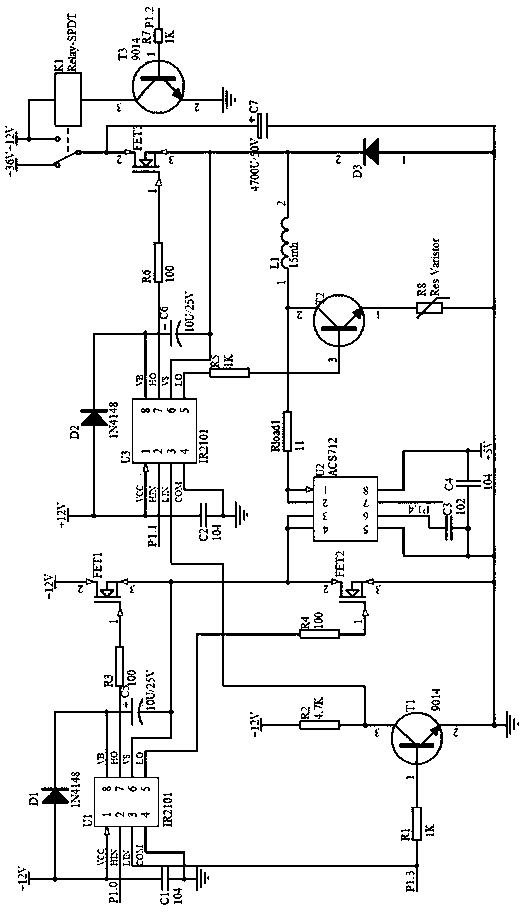
[0028] According to the CAN bus-based motor bench experimental device described in embodiment 1, the excitation controller has a single-chip microcomputer inside, the CAN bus interface of the single-chip microcomputer, the CAN communication interface of the motor controller and the The CAN analyzer is connected, the front end of the torque sensor has a signal output terminal, and the signal output terminal is connected to the excitation controller through a wire.

Embodiment 3

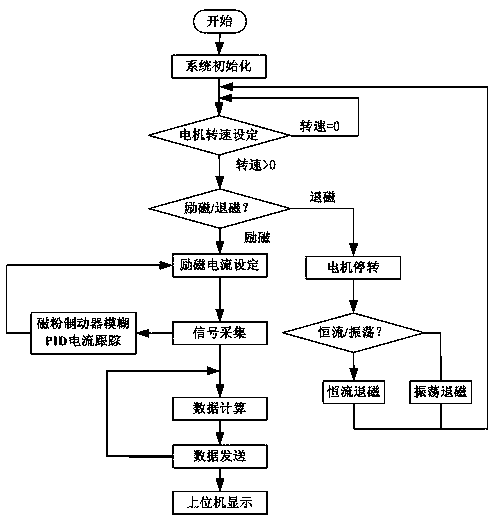
[0030] A load control method using the CAN bus-based motor bench test device described in Example 1-2. This method is: firstly, the computer, CAN analyzer, excitation controller, magnetic powder brake, torque sensor, and The measuring motor is installed on the bench, and the virtual instrument software LabVIEW is used to design the upper computer interface for the platform. The upper computer interface displays the motor speed, torque and excitation current in real time, realizes continuous adjustment of the magnetic powder brake excitation current, and controls the motor speed , Excitation / demagnetization function switch, choice of two demagnetization methods, display demagnetization curve, real-time display of data information transmitted by CAN bus, data can be stored in the form of graphs, tables, etc.;

[0031] The CAN analyzer is connected to the computer through a USB interface to realize bus two-way data transmission, receive computer instructions, upload the collected sys...


PUM


Abstract

The invention relates to a CAN bus-based motor bench experiment device and a load control method. The traditional magnetic powder brake has two demagnetization modes, in a situation with low precisionrequirements, a reverse constant current demagnetization mode is adopted, and in a situation with high precision requirements, a sinusoidal oscillation demagnetization mode is adopted. The CAN bus-based motor bench experiment device comprises the magnetic powder brake (5); the magnetic powder brake has an excitation control end interface; the excitation control end interface is connected with anexcitation controller (4) through a wire; the excitation controller is connected with a CAN analyzer (2) through a CAN bus (3); the CAN analyzer is connected with a computer (1) through a USB interface; the magnetic powder brake is connected with a torque sensor (7) through a coupling A (6); the torque sensor is connected with a tested motor (9) through a coupling B (8); and the tested motor is connected with a motor controller (10) through a wire. Thus, the CAN bus-based motor bench experiment device is arranged.

Description

Technical field: [0001] The invention relates to a CAN bus-based motor bench experimental device and a load control method. Background technique: [0002] There are two traditional demagnetization methods for magnetic powder brakes. For applications with low accuracy requirements, the reverse constant current demagnetization method can be used, and for applications with high accuracy requirements, a sinusoidal oscillation demagnetization method is required. The performance of tracking the target excitation current of the magnetic powder brake directly affects the accuracy of the magnetic powder brake control system, and plays a decisive role in the accuracy of the motor experiment. Because the magnetic powder brake will have residual magnetism after each use, the existence of residual magnetism will affect the next The accuracy of an experiment requires demagnetization control of the magnetic powder brake. [0003] With the further improvement of motor design level and process lev...

Claims


Application Information

Patent Timeline
IPC IPC(8): G01R31/34G01R1/20
CPCG01R1/20G01R31/34
Inventor 周凯艾民金宁治刘金凤王旭东
Owner HARBIN UNIV OF SCI & TECH
Learn More