Automatic cooling box, automatic cooling power battery pack and new energy automobile

An automatic cooling and power battery technology, which is applied in the direction of batteries, secondary batteries, battery pack components, etc., can solve the problems of uneven cooling, low efficiency of cooling methods, unsuitable timing control, etc., and achieve the effect of simplifying the structure and reducing the time difference

Pending Publication Date: 2018-11-09
SHANDONG XINHEYUAN HEAT TRANSFERRING TECH
View PDF0 Cites 1 Cited by
  • Summary
  • Abstract
  • Description
  • Claims
  • Application Information

AI Technical Summary

Problems solved by technology

[0005] The technical task of the present invention is to address the above deficiencies and provide an automatic cooling box, an automatic cooling power battery pack and a new energy vehicle to solve the problems of low efficiency, unsuitable timing and uneven cooling of the existing power battery cooling methods

Method used


Image

  • Automatic cooling box, automatic cooling power battery pack and new energy automobile
  • Automatic cooling box, automatic cooling power battery pack and new energy automobile
  • Automatic cooling box, automatic cooling power battery pack and new energy automobile

Examples


Embodiment 1

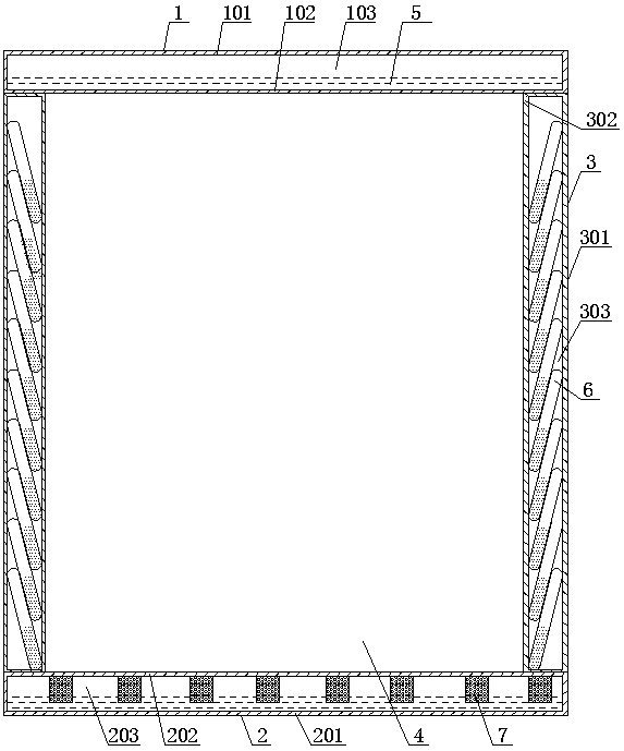
[0041] As attached figure 1 As shown, an automatic cooling box includes a top wall 1, a bottom wall 2, and a vertical wall 3, and a cavity 4 surrounded by the top wall 1, the bottom wall 2 and the vertical wall 3. The cavity 4 can accommodate a new energy battery. The side wall of the top wall 1, the bottom wall 2 and the vertical wall 3 close to the cavity 4 is the inner side wall, and the side wall of the top wall 1, the bottom wall 2 and the vertical wall opposite to the inner side wall is the outer side wall.

[0042] The top wall 1 is a hollow wall. The hollow cavity 103 of the top wall is provided with a liquid phase change medium 5. The liquid phase change medium 5 exchanges heat with the heat in the box through the inner side wall 102 of the top wall. The wall 102 is used as the heat absorption wall, and the outer side wall 101 of the top wall is used as the exothermic wall. When the temperature in the box body reaches the boiling point of the liquid phase change medium 5,...

Embodiment 2

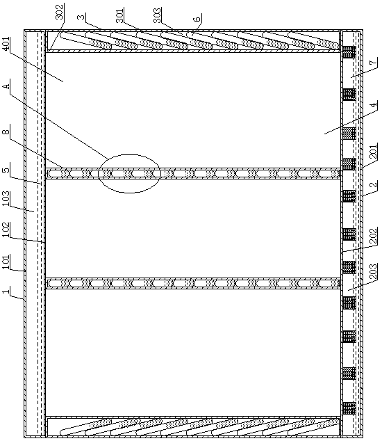
[0053] As attached figure 2 And image 3 As shown, this embodiment is a further improvement on the basis of embodiment 1. The difference between this embodiment and embodiment 1 is: the cavity 4 is equipped with two vertical partitions 8, and the two partitions 8 divide the cavity The body 4 is divided into three sub-cavities from left to right, and each sub-cavity can accommodate a new energy battery.

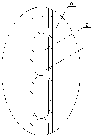
[0054] In order to improve the heat dissipation in the box, the partition 8 is set as a heat conducting plate. Specifically, the partition 8 is a hollow plate, and a plurality of closed heat conduction pipes 9 arranged vertically are arranged in the hollow cavity of the partition 8, and each heat conduction pipe 9 is provided with a liquid phase change medium 5, a heat conduction pipe 9 The gap is set in the hollow cavity of the partition 8, that is, one side of the heat pipe 9 is in contact with the outer side wall of the near partition 8, and the other phase side of the heat p...

Embodiment 3

[0060] As attached Figure 5 As shown, an automatic cooling power battery pack includes a power battery 11 and an automatic cooling box as described in Embodiment 1. The power battery 11 is assembled in a cavity 4. In this embodiment, the power battery 11 is three groups of power battery packs, and the three groups of power battery packs are assembled in the cavity 4.

[0061] In this embodiment, an automatic cooling battery pack can automatically cool down. The automatic cooling method is specifically as follows: when the power battery 11 generates heat and causes the temperature in the cavity 4 to rise, when the temperature reaches the boiling point of the liquid phase phase change medium, the top wall 1. The phase change medium of the liquid phase in the bottom wall 2 and the vertical wall 3 exchanges heat with the heat in the cavity 4 through the inner side wall, and the phase change medium of the liquid phase absorbs heat and vaporizes into the phase change medium of the gas ...


PUM


Abstract

Belonging to the field of new energy batteries, the invention discloses an automatic cooling box, an automatic cooling power battery pack and a new energy automobile to solve the technical problems oflow cooling mode efficiency, inappropriate time control and uneven cooling in existing power batteries. The structure of the automatic cooling box includes a top wall, a bottom wall and a vertical wall, as well as a cavity enclosed by the top wall, the bottom wall and the vertical wall. The top wall, the bottom wall and the vertical wall are all hollow walls, and the hollow cavity of the top wallis internally equipped with a liquid phase change medium. The hollow cavity of the bottom wall is internally equipped with a liquid phase change medium and is equipped with a diversion mechanism. Thehollow cavity of the vertical wall is internally equipped with a plurality of inclined closed heat transfer tubes, and each heat transfer tube is internally equipped with a liquid phase change medium, which is a phase change medium with low boiling point. The automatic cooling power battery pack includes a power battery and the automatic cooling box. The new energy automobile includes the automatic cooling power battery pack. The box can automatically uniformize the temperature of the power battery and timely and controllably lower the temperature.

Description

Technical field [0001] The invention relates to the field of battery boxes, in particular to an automatic cooling box, an automatic cooling power battery pack and a new energy vehicle. Background technique [0002] The power battery will generate heat during use. Overheating will cause the power battery to accelerate degradation and even cause an explosion. Too low temperature will cause the power battery's efficiency to be too low. Therefore, it is necessary to ensure that the power battery is in a certain temperature environment. [0003] Existing power battery cooling methods include self-heating air cooling, forced electric cooling, and water cooling. Natural air cooling has the problems of low efficiency, inability to accurately control the start timing, and the inability to achieve uniform temperature of the power battery Problem: The forced electric cooling method cannot ensure that the entire power battery is cooled as a whole, and there is a problem that the temperature of...

Claims


Application Information

Patent Timeline
IPC IPC(8): H01M10/613H01M10/617H01M10/625H01M10/6569H01M10/6554H01M10/6556H01M2/10
CPCH01M10/613H01M10/617H01M10/625H01M10/6554H01M10/6556H01M10/6569H01M2220/20H01M50/20Y02E60/10
Inventor 张洪延张志强
Owner SHANDONG XINHEYUAN HEAT TRANSFERRING TECH
Why Eureka
Try Eureka