Antenna system and mobile terminal

An antenna system and mobile terminal technology, applied in the direction of antenna, antenna grounding device, independent antenna unit combination, etc., can solve the problems of thickening the whole mobile terminal, increasing the antenna layout area, increasing the antenna design cost, etc. Light and thin body, reduce design cost, and save antenna layout area

Active Publication Date: 2018-11-13
ONEPLUS TECH SHENZHEN
View PDF12 Cites 25 Cited by
  • Summary
  • Abstract
  • Description
  • Claims
  • Application Information

AI Technical Summary

Problems solved by technology

This multi-band antenna implementation method needs to be realized by adding radio frequency devices (for example, antenna brackets) and LDS (Laser Direct Structuring, laser direct structuring) devices, but this method will increase the layout area of ​​the antenna and lead to thicker mobile terminals , does not meet the requirements of slim appearance, and this method will inevitably increase the cost of antenna design

Method used


Image

  • Antenna system and mobile terminal
  • Antenna system and mobile terminal
  • Antenna system and mobile terminal

Examples


no. 1 example

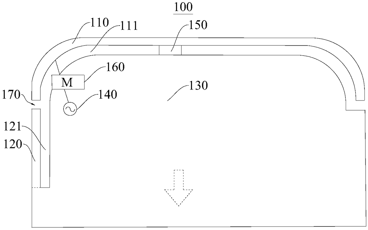
[0039] Please refer to figure 1 , is a schematic diagram of the first structure of the antenna system 100 provided by the embodiment of the present invention. In the embodiment of the present invention, the antenna system 100 can provide a mobile terminal with an antenna to realize multi-band signal communication, save the antenna layout area in the mobile terminal, reduce the antenna design cost of the mobile terminal, and benefit the mobile terminal Realization of thin and light body characteristics. Wherein, the antenna system 100 includes a metal floor 130 , a first metal frame 110 , a second metal frame 120 , a matching network 160 , a connecting rib 150 and a radio frequency signal source 140 .

[0040] In this embodiment, the first metal frame 110 and the metal floor 130 are separated from each other, and the ribs 150 are arranged between the first metal frame 110 and the metal floor 130, and are connected to the metal floor 130 respectively. The first metal frame 110...

no. 2 example

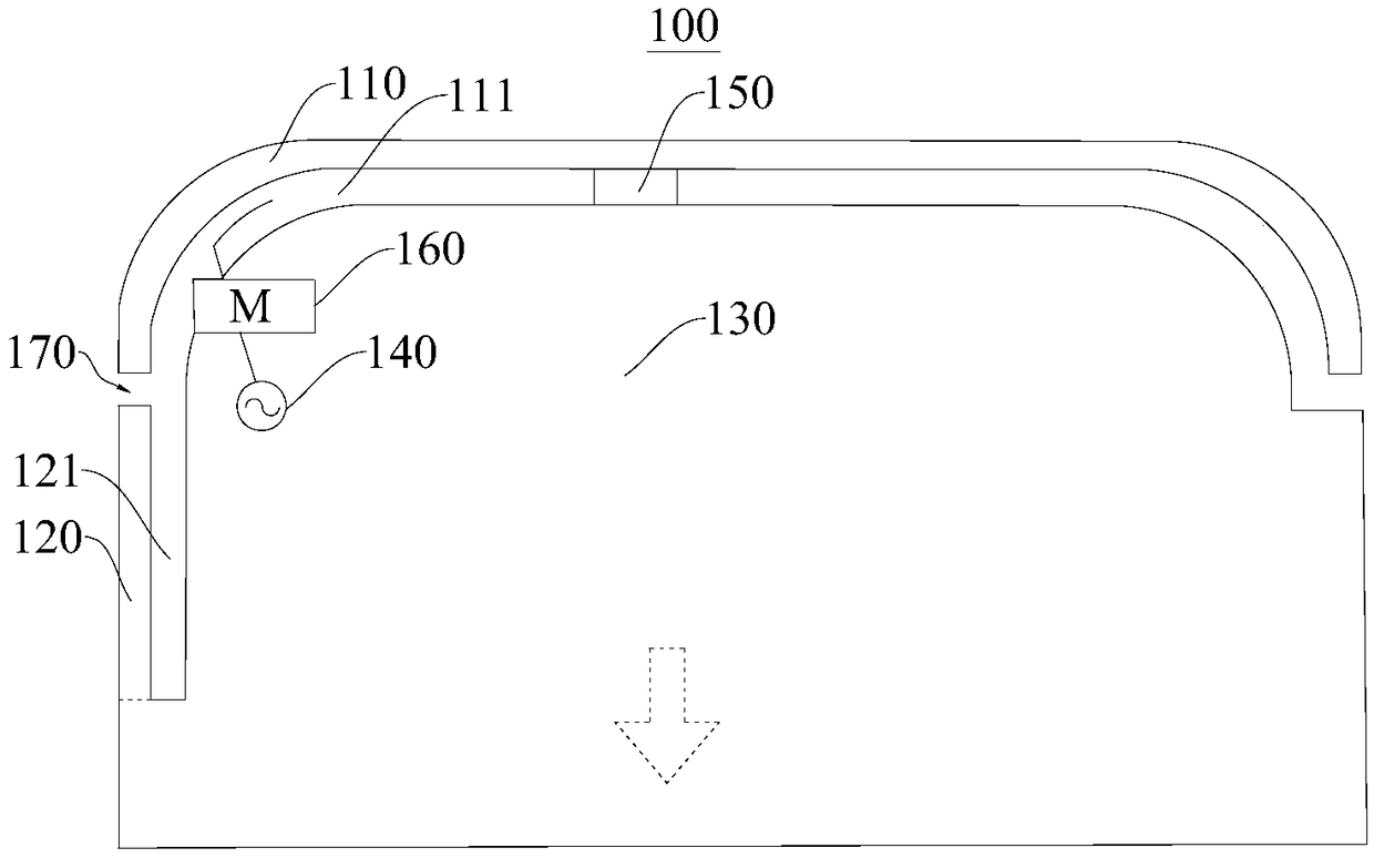
[0056] Please refer to figure 2 , is a second schematic structural diagram of the antenna system 100 provided by the embodiment of the present invention. In the embodiment of the present invention, figure 2 The shown antenna system 100 is similar to that of figure 1The illustrated antenna system 100 is similar except that, figure 2 In the antenna system 100 shown, the matching network 160 adopts a coupling feeding method for the feeding method of the first metal frame 110 .

[0057] Optionally, in this embodiment, the antenna system 100 may set a coupling stub in the first slot 111 close to the corresponding feeding position on the first metal frame 110, and the matching network 160 connects the stubs The coupling stub, so that the RF signal source 140 forms a coupling excitation with the first metal frame 110 based on the coupling stub connected with the matching network 160, ensuring that the first metal frame 110 is connected to the first metal frame 110 under the act...

no. 3 example

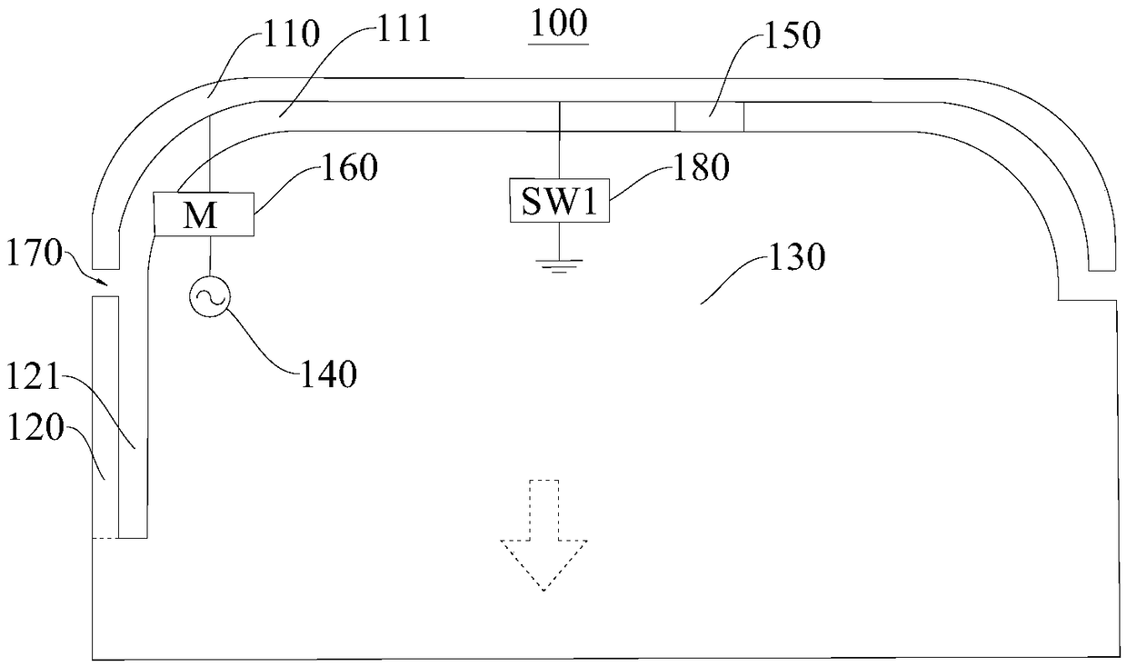
[0059] Please refer to image 3 , is a schematic diagram of a third structure of the antenna system 100 provided by the embodiment of the present invention. In the embodiment of the present invention, image 3 The shown antenna system 100 is similar to that of figure 1 The illustrated antenna system 100 is similar except that, image 3 The illustrated antenna system 100 may also include a first antenna switch 180 .

[0060] In this embodiment, one end of the first antenna switch 180 is connected to the first metal frame 110, and the other end of the first antenna switch 180 is connected to the metal floor 130, for The resonant frequency corresponding to the first antenna substructure of a metal frame 110 is tuned. Wherein, the first antenna switch 180 can control the first resonant frequency f corresponding to the first metal frame 110 1 and the second resonant frequency f 2 Tuning is performed so that the first antenna structure corresponding to the first metal frame 11...


PUM


Abstract

The invention provides an antenna system and a mobile terminal. A first metal frame of the antenna system is connected with a metal floor through connection bar positions; a first slot is formed between the first metal frame and the metal floor; one end of a second metal frame is connected with the metal floor; the second metal frame is extended parallel to the lateral side of the metal floor; a second slot is formed between the second metal frame and the metal floor; the end of the first metal frame faces the end of the second metal frame; a slot for providing coupling excitation is arrangedbetween the opposing ends of the first and second metal frames. A radio frequency signal source is electrically connected with the first metal frame or the second metal frame through a matching network so as to form a multi-frequency antenna. The antenna system herein can provide multi-frequency signal communication through one antenna, antenna layout area is saved, antenna design cost is reduced,and implementation of a light and thin body of the mobile terminal is benefited.

Description

technical field [0001] The present invention relates to the technical field of multi-band antennas, in particular to an antenna system and a mobile terminal. Background technique [0002] With the continuous development of mobile terminals, people have higher requirements for the appearance size and equipment performance of mobile terminals. At present, mobile terminals that are widely concerned by people need to be thin and light and capable of supporting multi-band antennas (for example, GPS antenna, WIFI 2.4G antenna, WIFI 5G antenna, etc.) communication characteristics. For the multi-band antenna communication function of mobile terminals, the market usually uses three different frequency band signals to be split into two antennas, one of the two antennas works in dual frequency, and the other works in single frequency. And adjust the corresponding frequency band mode of each antenna according to the demand, and realize the communication function of multi-band signal th...

Claims


Application Information

Patent Timeline
Patent Type & Authority Applications(China)
IPC IPC(8): H01Q1/36H01Q1/44H01Q1/48H01Q1/50H01Q5/10H01Q5/328H01Q21/30
CPCH01Q1/36H01Q1/44H01Q1/48H01Q1/50H01Q21/30H01Q5/10H01Q5/328
Inventor 李杰山周昌文
Owner ONEPLUS TECH SHENZHEN
Why Eureka
Try Eureka