Thermoplastic composite material automatic placement device and method thereof

A composite material and thermoplastic technology, which is applied in the field of thermoplastic composite material automatic laying device, can solve the problems of low connection strength, slow laying speed, difficult control of processing temperature, etc., and achieve precise heating area, fast heating speed, saving laying The effect of molding time

Active Publication Date: 2018-11-16
CHANGCHUN UNIV OF SCI & TECH
View PDF8 Cites 7 Cited by
  • Summary
  • Abstract
  • Description
  • Claims
  • Application Information

AI Technical Summary

Problems solved by technology

[0008] In order to achieve the above purpose, the present invention provides a thermoplastic composite material automatic laying device and method, which solves the

Method used


Image

  • Thermoplastic composite material automatic placement device and method thereof
  • Thermoplastic composite material automatic placement device and method thereof
  • Thermoplastic composite material automatic placement device and method thereof

Examples


Embodiment 1

[0052] The aramid fiber / PA prepreg tape 10 with a size of 0.5mm×12mm is automatically laid by a composite material automatic laying device, which specifically includes the following steps:

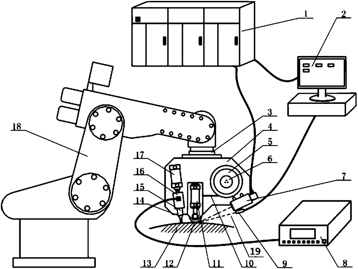
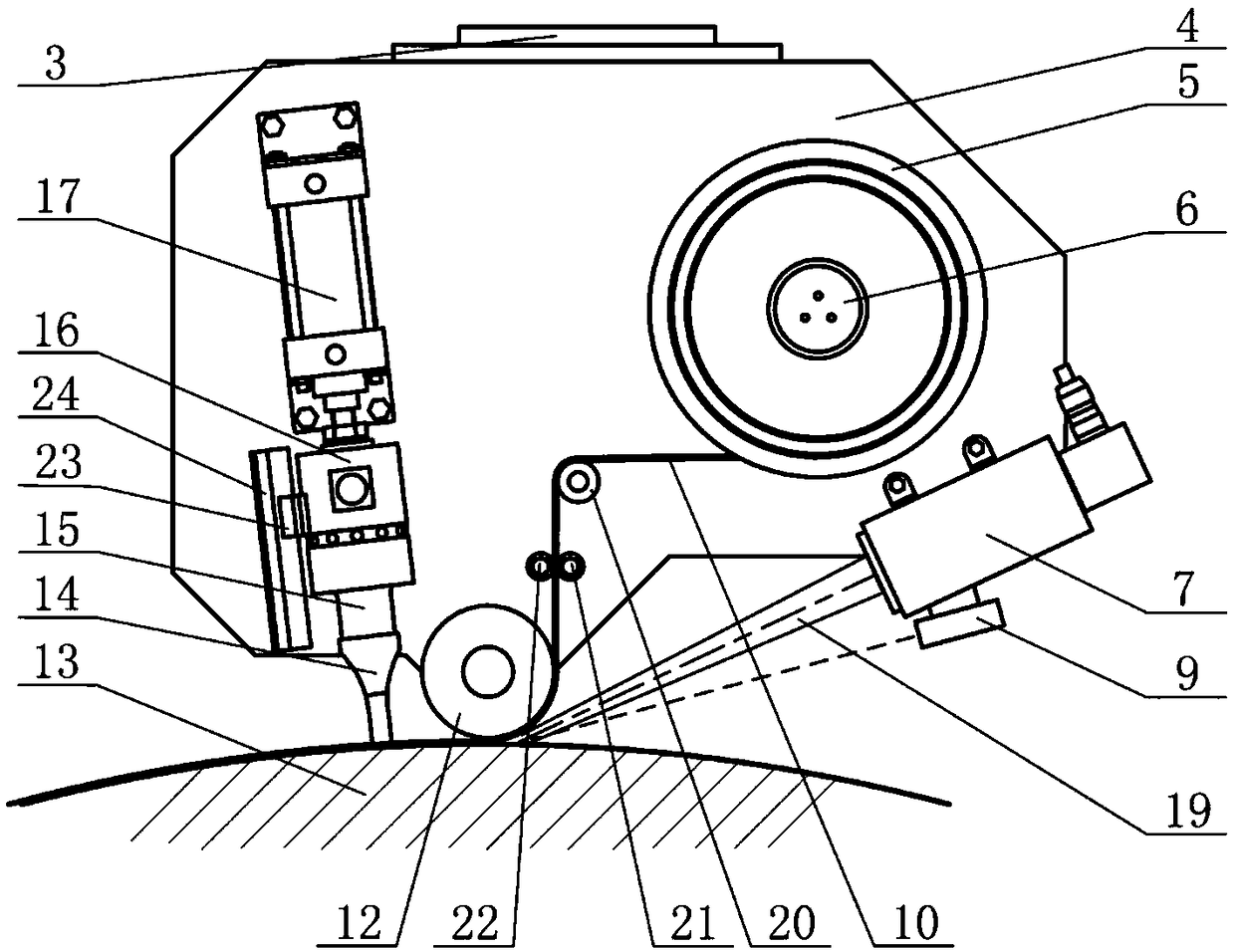
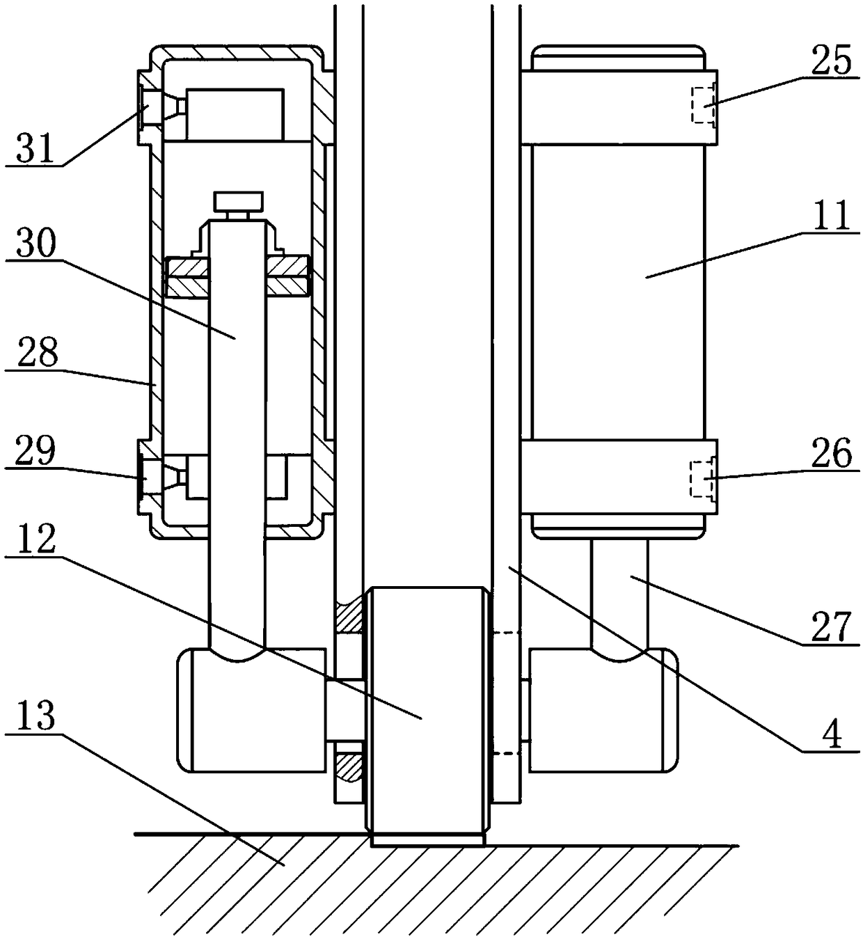
[0053] Step 1: The robot 18 pulls and installs the support plate 4 of the laying device, laser welding device and ultrasonic vibration device to the top of the substrate 13, and the aramid / PA prepreg tape 10 passes through the guide wheel 20, the main driving roller 21 and the auxiliary driving roller 22 Transfer to below the pressure roller 12, the first air hole 25 and the fourth air hole 31 intake air, the second air hole 26 and the third air hole 29 exhaust, the first piston rod 27 and the second piston rod 30 push the pressure roller 12, so that The aramid / PA prepreg tape 10 and the base material 13 are closely attached, and the pressure of the first air cylinder 11 and the third air cylinder 28 is adjusted so that the pressure of the pressure roller 12 on the aramid / PA prepreg tape 10...

Embodiment 2

[0058] The basalt fiber and carbon fiber blended / PE prepreg tape 10 with a size of 0.4mm×10mm is automatically laid by a composite material automatic laying device, which specifically includes the following steps:

[0059]Step 1: The robot 18 pulls and installs the support plate 4 of the placement device, laser welding device and ultrasonic vibration device to the top of the substrate 13, and the basalt fiber and carbon fiber blend / PE prepreg tape 10 passes through the guide wheel 20, the main driving roller 21 and The auxiliary drive roller 22 is conveyed to the bottom of the pressure roller 12, the first air hole 25 and the fourth air hole 31 take in air, the second air hole 26 and the third air hole 29 exhaust, and the first piston rod 27 and the second piston rod 30 push and pressurize The roller 12 makes the basalt fiber and carbon fiber blend / PE prepreg tape 10 and the base material 13 fit closely, adjusts and adjusts the pressure of the first air cylinder 11 and the thir...

Embodiment 3

[0064] The glass fiber / PP prepreg tape 10 with a size of 0.3mm×15mm is automatically laid by a composite material automatic laying device, which specifically includes the following steps:

[0065] Step 1: The robot 18 pulls and installs the support plate 4 of the laying device, laser welding device and ultrasonic vibration device to the top of the substrate 13, and the glass fiber / PP prepreg tape 10 passes through the guide wheel 20, the main driving roller 21 and the auxiliary driving roller 22 Transfer to below the pressure roller 12, the first air hole 25 and the fourth air hole 31 intake air, the second air hole 26 and the third air hole 29 exhaust, the first piston rod 27 and the second piston rod 30 push the pressure roller 12, so that The glass fiber / PP prepreg tape 10 is closely attached to the base material 13, and the pressure of the first air cylinder 11 and the third air cylinder 28 is adjusted so that the pressure of the pressure roller 12 on the glass fiber / PP pre...


PUM

PropertyMeasurementUnit
Shear strengthaaaaaaaaaa

Abstract

The invention discloses a thermoplastic composite material automatic placement device and a method thereof. The thermoplastic composite material automatic placement device comprises a placement device, and the placement device is mounted on a support plate, a laser welding head of a laser welding device is fixed on one side of the placement device, and an ultrasonic vibration device is fixed on the other side of the placement device; a thermoplastic prepreg tape wound on a reel by the placement device is conveyed to a pressure roller through a guiding wheel and main and auxiliary driving rollers, the pressure of the pressure roller is controlled, the thermoplastic prepreg tape is fully contacted with a substrate; the laser beam from the laser welding head obliquely irradiates at the junction of the thermoplastic prepreg tape and the substrate, and an infrared temperature probe detects the processing temperature and feeds back to a computer to control the processing temperature in realtime; an ultrasonic vibration device applies ultrasonic shock to the thermoplastic prepreg tape behind the pressure roller. The laser of the device is used as a heat source, and the heating area is precise, and the heating speed is fast; the ultrasonic energy is introduced to improve the interface connection strength; and the temperature closed-loop control is used to improve the quality of the processed part.

Description

technical field [0001] The invention belongs to the technical field of laser processing, and relates to a thermoplastic composite material automatic laying device and method. Background technique [0002] Structural parts made of high-performance composite fiber materials have the characteristics of high strength, light weight and corrosion resistance, and are widely used in aerospace, automobiles, electrical appliances, construction and other fields. Among them, thermoplastic resin-based composite materials have short curing time, greatly shorten the molding cycle, have the characteristics of strong impact toughness and good welding performance, and have received more and more attention and research. However, due to the high melting point and high viscosity of the resin base material, high temperature and high pressure are required for component molding, and the requirements for molding equipment are relatively strict, thus restricting its further promotion and use, and aut...

Claims


Application Information

Patent Timeline
IPC IPC(8): B29C70/38
CPCB29C70/386
Inventor 刘佳白陈明石岩李忠刘双宇刘凤德张宏
Owner CHANGCHUN UNIV OF SCI & TECH
Why Eureka
Try Eureka