
3D printing device boom system and debugging method

A 3D printing and jib technology, which is applied in the processing of building materials, construction, building construction, etc., can solve the problems of reduced printing accuracy and large deflection, and achieve the effect of small deflection and strong load-bearing capacity

Active Publication Date: 2019-01-01
SHANGHAI CONSTRUCTION GROUP +1
View PDF6 Cites 0 Cited by
  • Summary
  • Abstract
  • Description
  • Claims
  • Application Information

AI Technical Summary

Problems solved by technology

[0004] Aiming at the problem in the prior art that when the tower-type 3D printing device adopts a long arm frame for construction, the printing accuracy is reduced due to large deflection, the present invention provides a 3D printing device arm frame system and a debugging method, which can make the The arm frame achieves dynamic balance, effectively improving the positioning of the print head and printing accuracy

Method used


Image

  • 3D printing device boom system and debugging method
  • 3D printing device boom system and debugging method
  • 3D printing device boom system and debugging method

Examples


Embodiment 1

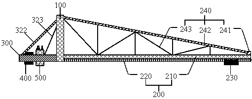
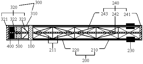
[0057] see Figure 1 to Figure 3 , the present invention provides a 3D printing device arm frame system, including a vertically arranged door frame 100, a boom frame 200 and a balance arm frame 300 respectively arranged on both sides of the door frame 100, and a balance arm frame 300 arranged on the The standard counterweight assembly 400 on, and the hydronic balance assembly 500.

[0058] Wherein, the boom frame 200 includes a boom beam 210, a guide rail 220 arranged below the boom beam 210, and a horizontal drive braking device for the print head that can move horizontally along the guide rail 220 is provided on the guide rail 220. 230. combine figure 1 and figure 2 As shown, the boom beams 210 are two groups parallel to each other, the two groups of boom beams 210 are fixedly connected by a plurality of reinforcing rods 211 , and the boom beams 210 are formed into a stable whole by a plurality of reinforcing rods 211 . The boom frame 200 also includes an upper arm fram...

Embodiment 2

[0068] When printing the main structure of a 3D building, such as a 1m×1m support column, the diameter of the 3D printing head may reach 30cm or more, and the weight of the 3D printing head is relatively heavy. When the 3D printing head runs along the guide rail 220, the boom frame 200 The change of the torque above is relatively large, and the inflow flow control valve 521 / outflow flow control valve 531 needs a large adjustment range. When printing auxiliary structures on the wall, it is possible to replace it with a print head with a diameter of 3 cm. The weight of the 3D print head is small, and the moment change on the boom frame 200 is small when running along the guide rail 220, and the flow into the flow control valve 521 / The outflow flow control valve 531 requires a smaller adjustment range and higher adjustment accuracy.

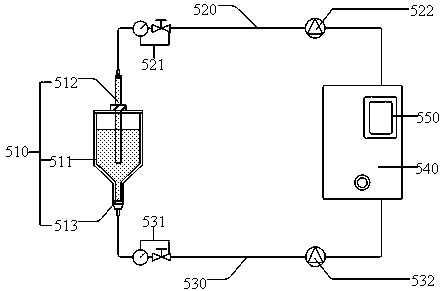
[0069] For this, as Figure 4 As shown, in the 3D printing device arm support system provided in this embodiment, the liquid circulation balance ...

Embodiment 3

[0071] The present invention also provides a debugging method for the arm support system of the 3D printing device as in Embodiment 1, the following will be combined with the attached Figures 1 to 4 This debugging method is further introduced. This debugging method includes:

[0072] Step 1: Determine the mass of the standard counterweight assembly 400 through static load calculation m 1 . In the case that the printing head horizontal drive braking device 230 is located at the end of the guide rail 220 close to the door frame 100 and the 3D printing head is installed, according to the moment balance on the boom frame 200 and the balance arm frame 300 and the distance between the standard counterweight assembly 400 and the door frame A distance of 100 determines the mass of the standard counterweight assembly 400 m 1 . From Example 1, it can be seen that . A standard weight assembly 400 can include a plurality of weights with a total mass of m 1 , The position of th...


PUM


Abstract

The invention relates to a 3D printing device arm frame system and a debugging method, and belongs to the technical field of 3D printing in building construction. The 3D printing device arm frame system comprises a portal frame, a lazy arm frame and a balance arm frame, a standard counterweight assembly and a liquid circulation balance assembly, wherein the portal frame is vertically arranged, thelazy arm frame and the balance arm frame are arranged on both sides of the portal frame, and the standard counterweight assembly is arranged on the balance arm frame. The debugging method for the 3Dprinting device arm frame system comprises the following steps that mass of the standard counterweight assembly is determined through static load calculation; the relationship between an inflow or outflow Q1 and a speed V is determined when a print head horizontal drive braking device moves at a constant speed V according to dynamic load calculation; and in 3D printing construction, the moment ofthe lazy arm frame and the balance arm frame on both sides of the portal frame is kept in dynamic balance by controlling the inflow or outflow Q1. According to the 3D printing device arm frame systemand the debugging method, the dynamic balance of the moment of the arm frame in an uniform motion or uniform acceleration motion of a 3D printing head can be realized, and thus high-precision positioning in the printing process is ensured, and guarantee for realizing printing construction of large buildings providing is provided.

Description

technical field [0001] The invention relates to a 3D printing device boom system and a debugging method, belonging to the technical field of 3D printing in building construction. . Background technique [0002] The degree of mechanization and automation of the traditional construction industry is low, and its development urgently needs transformation and upgrading. With the development and maturity of 3D printing technology, this technology will bring technological innovation to the labor-intensive construction industry. Architectural 3D printing technology has the characteristics of high degree of mechanization and automation, one-time molding, less construction consumables and process loss, etc. Way, its research has become the development trend of the construction industry. [0003] The tower type 3D printing device is an available device for architectural 3D printing, which has the characteristics of light weight and standardized assembly and disassembly. However, th...

Claims


Application Information

Patent Timeline
Patent Type & Authority Patents(China)
IPC IPC(8): E04G21/00B33Y30/00B33Y40/00
CPCB33Y30/00B33Y40/00E04G21/00
Inventor 龚剑黄玉林张桂娟左自波占羿箭潘曦杜晓燕
Owner SHANGHAI CONSTRUCTION GROUP
Learn More