
Automatic pipe supporting device

A technology for installing plates and oil cylinders, which is used in drill pipes, casings, drilling equipment, etc., and can solve the problems of low efficiency, single movement and flexible movement of manipulators.

Active Publication Date: 2018-11-16
无锡市盛宝嘉科技有限公司
View PDF6 Cites 4 Cited by
  • Summary
  • Abstract
  • Description
  • Claims
  • Application Information

AI Technical Summary

Problems solved by technology

[0005] In the prior art, there are also some situations where automatic pipe-handling manipulators are used for pipe-handling operations, but most of these pipe-handling manipulators are fixedly installed on the drill floor, the manipulator cannot move, the efficiency of manipulator hand-handling is low, and it is easy to cause Personnel collisions cause safety hazards; although some manipulators can move, they can only move in a single direction on the drill floor. This type of manipulator also cannot be flexible according to needs due to the single movement form when performing pipe-elevating operations. movement, resulting in less efficient buttresses

Method used


Image

  • Automatic pipe supporting device
  • Automatic pipe supporting device
  • Automatic pipe supporting device

Examples


Embodiment Construction

[0087] In order to make the present invention achieve the above objects, features and advantages and make it more obvious and understandable, the present invention will be further described in detail below in conjunction with the accompanying drawings.

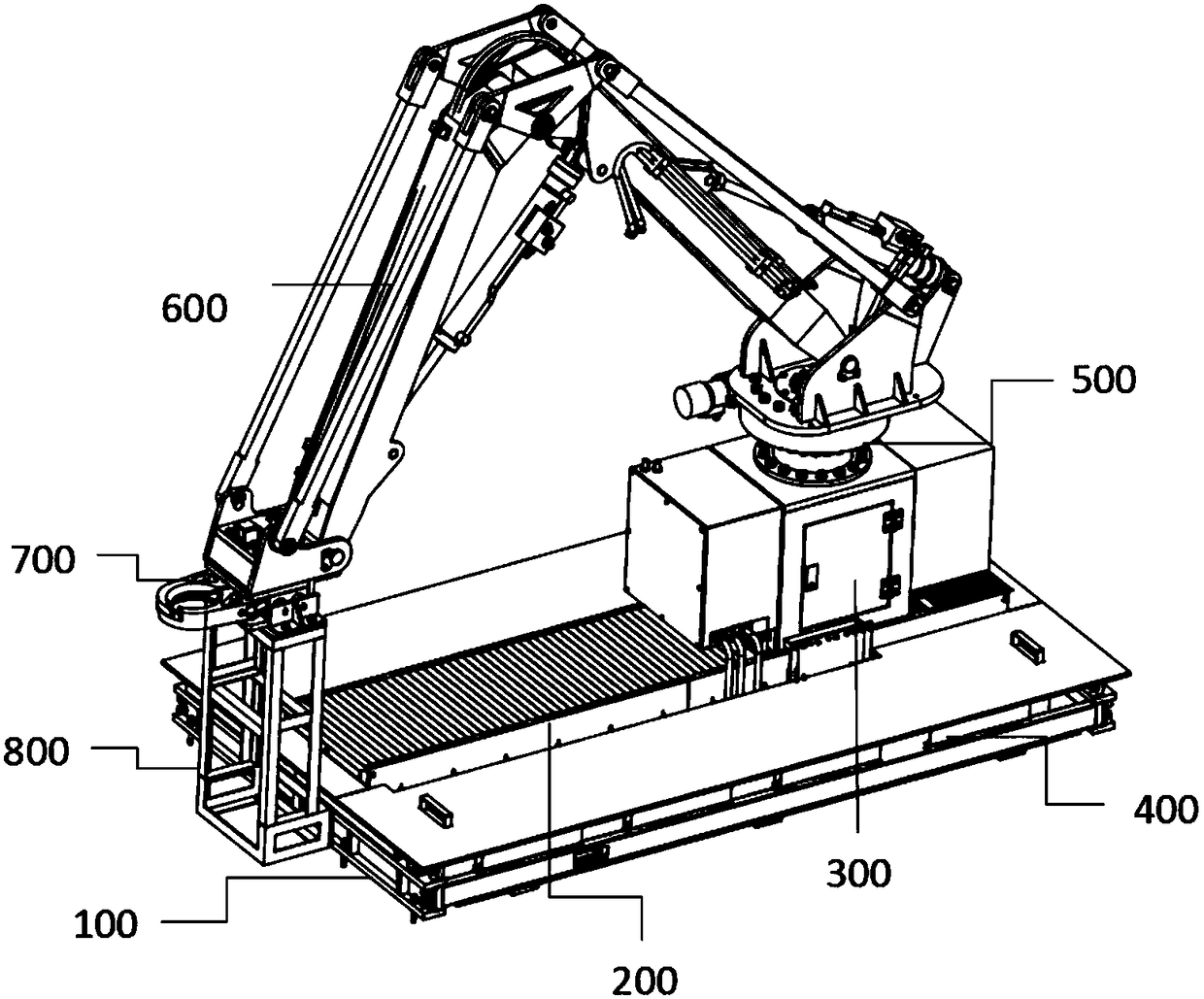
[0088] Such as Figure 1-2 , the automatic pipe support device of the present invention includes a platform part 100, a ground rail part 200, a motor part 300, a drag chain part 400, a base part 500, a mechanical arm 600 and a claw part 700;

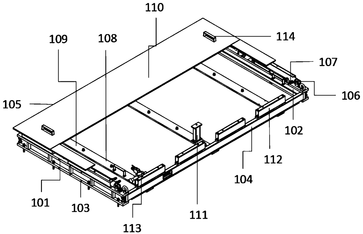
[0089] The platform portion 100 includes a platform frame 101; the platform frame 101 is a square frame consisting of a front side beam 102, a rear side beam 103, a left side beam 104 and a right side beam 105; Oil cylinder 106; the oil cylinder 106 is connected with a straight joint 107 and a hinge shaft 108; the oil cylinder 106 is installed on the left end of the front side beam 102, the straight joint 107 is installed on the left end of the oil cylinder 106 and the hinge shaft 108 is...


PUM


Abstract

The invention discloses an automatic pipe supporting device, and belongs to the technical field of mechanical automation. The automatic pipe supporting device comprises a platform part, a ground railpart, a motor part, a drag chain part, a base part, a mechanical arm and a claw part. The automatic operations such as discharging, taking out, root standing of a drill pipe, a drill collar and a casing of an oil drilling platform surface can be realized, and the automatic pipe supporting device can be further adapted to the pipe supporting operation of a pipe column up and down the drilling platform surface at a ramp and a catwalk. The automatic pipe supporting device can replace manual pipe supporting operation of the drilling platform surface, and has the advantages of reducing the labor intensity of the pipe supporting operation and improving the efficiency and safety of the pipe supporting operation.

Description

technical field [0001] The invention relates to an automatic pipe supporting device, which belongs to the technical field of mechanical automation. Background technique [0002] At present, the pipe support operation on the drilling floor of my country's oil drilling is mainly through manual pipe support, which has a low degree of automation and requires multiple operators to assist in the work of loading the drill pipe, drilling the drill pipe into the hole, arranging columns, and lowering the columns, which wastes manpower and work. less efficient. [0003] Moreover, there will be rockfall during the oil drilling process, and there will be a risk of being injured during manual assistance operations; the drill pipe is relatively long, and the swing of the drill pipe is relatively large. If the drill pipe is dumped, it will also cause injury to people, and the safety hazard is greater Big. [0004] Therefore, in order to improve the work efficiency of pipe support and reduc...

Claims


Application Information

Patent Timeline
Patent Type & Authority Applications(China)
IPC IPC(8): E21B19/14E21B19/15
CPCE21B19/14E21B19/146E21B19/155
Inventor 刘国文
Owner 无锡市盛宝嘉科技有限公司
Learn More