Ground wave over-the-horizon radar power range assessment method based on equivalent noise coefficient

A ground wave beyond-the-horizon and equivalent noise technology, which is applied to radio wave measurement systems, instruments, etc., can solve the problems of complex calculations and the inability to evaluate the range of power, etc., to solve complex calculations, avoid repeated calculations, and reduce the amount of calculations Effect

Active Publication Date: 2018-11-16
HARBIN INST OF TECH
View PDF8 Cites 8 Cited by
  • Summary
  • Abstract
  • Description
  • Claims
  • Application Information

AI Technical Summary

Problems solved by technology

[0007] The purpose of the present invention is to solve the disadvantages of complex calculations in the prior art and the inability to directly evaluate the power range through noise and clutter background strength, and propose a method for evaluating the power range of ground-wave over-the-horizon radar based on the equivalent noise figure

Method used


Image

  • Ground wave over-the-horizon radar power range assessment method based on equivalent noise coefficient
  • Ground wave over-the-horizon radar power range assessment method based on equivalent noise coefficient
  • Ground wave over-the-horizon radar power range assessment method based on equivalent noise coefficient

Examples


specific Embodiment approach 1

[0035] Specific implementation mode one: the ground-wave over-the-horizon radar power range evaluation method based on the equivalent noise figure comprises the following steps:

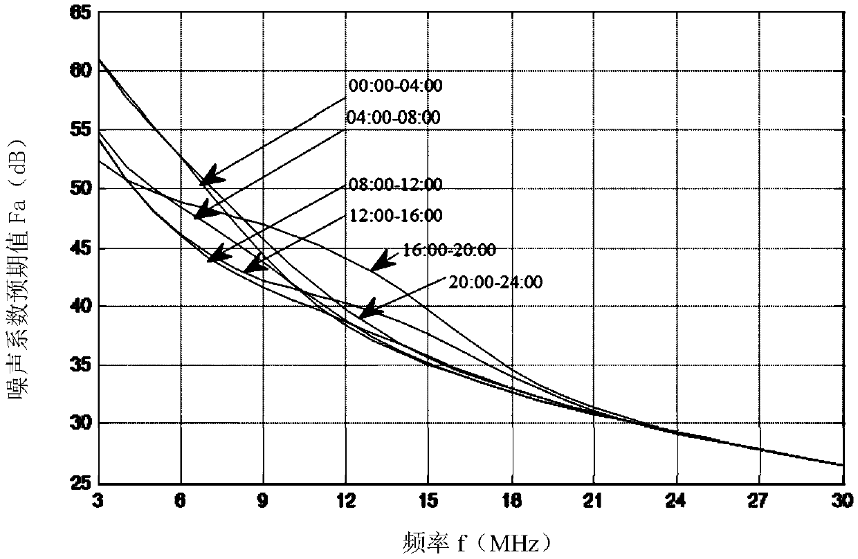
[0036] Step 1: The detection background of the ground wave over-the-horizon radar includes two parts: noise and clutter, expressed as the environmental noise power P n (p,f,t) and clutter power P c The sum of (p, f, t), that is, the detection background base power P nc (p, f, t); when noise and clutter exist at the same time, the radar equation is expressed in the form of signal-to-noise ratio SCNR;

[0037] Said p is the erection site of the radar, f is the operating frequency of the radar, and t is the operating time of the radar;

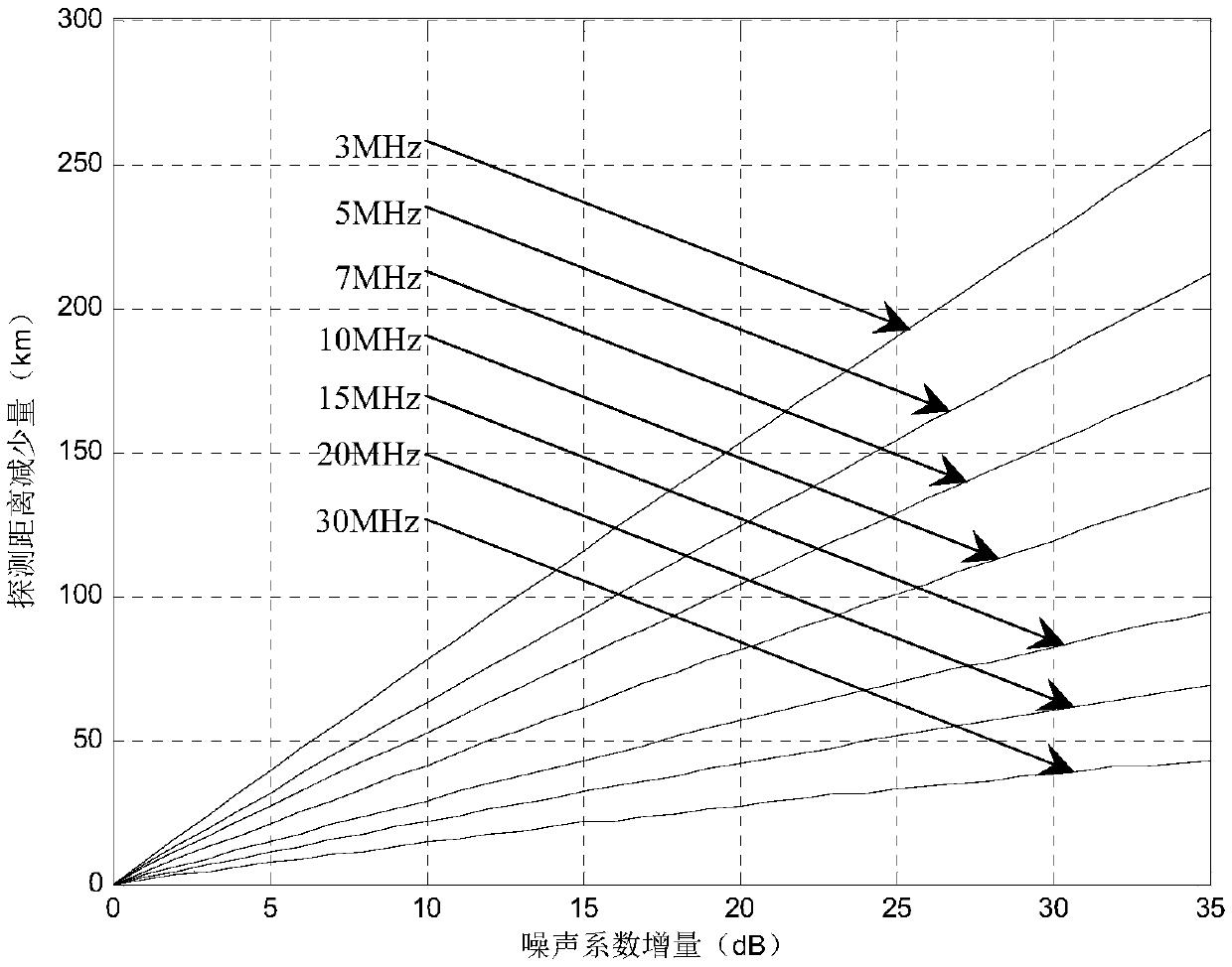
[0038] Step 2: According to the radar equation expressed in the form of signal-to-noise-noise ratio (SCNR) obtained in step 1, consider radar system parameters, time, location and other factors, and set the radar system signal-to-noise ratio detection threshold SCNR 0 ...

specific Embodiment approach 2

[0053] Specific embodiment two: the difference between this embodiment and specific embodiment one is: the detection background base of the ground wave over-the-horizon radar in the step one includes noise and clutter two parts, expressed as the environmental noise power P n (p,f,t) and clutter power P c The sum of (p, f, t), that is, the detection background base power P nc (p, f, t); when noise and clutter exist at the same time, the specific process of expressing the radar equation in the form of signal-to-noise ratio SCNR is:

[0054] Detect background base power P nc (p,f,t) is expressed as:

[0055] P nc (p,f,t)=P n (p,f,t)+P c (p,f,t)

[0056] When noise and clutter exist at the same time, the radar equation is expressed in the form of signal-to-noise ratio SCNR:

[0057]

[0058] Where SCNR is the signal-to-noise ratio of the target echo at a distance R, P t is the peak transmit power, γ is the duty cycle of the transmit signal, G t is the transmit antenna ...

specific Embodiment approach 3

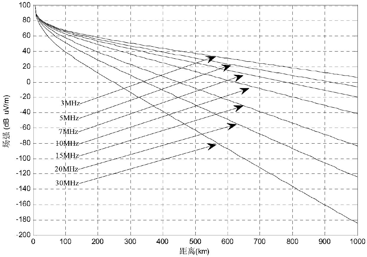
[0061] Specific implementation mode three: the difference between this implementation mode and specific implementation mode one or two is: in the said step two, according to the radar equation expressed in the form of signal-to-noise-to-noise ratio (SCNR) obtained in step one, the radar system signal-to-noise-noise ratio detection is set Threshold SCNR 0 , the expression of the ground wave field strength E(R) is:

[0062]

[0063] where SCNR 0 is the SNR detection threshold corresponding to the maximum detection distance (minimum SNR).

[0064] Other steps and parameters are the same as those in Embodiment 1 or Embodiment 2.


PUM


Abstract

The present invention provides a ground wave over-the-horizon radar power range assessment method based on an equivalent noise coefficient, and the present invention relates to a ground wave over-the-horizon radar power range assessment method. The problem is solved that a current technology is complex in calculation and cannot directly assess the power range through the noise and clutter background intensity. Through derivation and fitting, in an over-the-horizon detection area, a detection distance variation [Delta]R and a noise coefficient variation [Delta]F are approximate to a linear relation to obtain slopes kRF of the two so as to obtain the variation of a radar system detection distance according to the variation of the equivalent noise coefficient relative to an expected value andsolve the problem that a traditional method is complex in calculation. The ground wave over-the-horizon radar power range assessment method only needs a simple linear operation to assess the power range so as to avoid repetitive computation, effectively improve the practicability, reduce the calculated amount and to be simple and convenient in actual application. The ground wave over-the-horizonradar power range assessment method is used in the ground wave over-the-horizon radar detection field.

Description

technical field [0001] The invention relates to the field of ground-wave over-the-horizon radar detection, in particular to a method for evaluating the power range of ground-wave over-the-horizon radar. Background technique [0002] Ground-wave over-the-horizon radar uses the characteristics of high-frequency vertically polarized electromagnetic waves diffracting and propagating along the ocean surface to detect targets below the line of sight. Different operating frequencies of radars and different external electromagnetic environments will lead to different detection powers of radars. The external electromagnetic environment of ground-wave over-the-horizon radar is complex, which is closely related to the radar's erection location, working frequency, and working time. Its detection background includes environmental noise and clutter interference. Clutter interference includes sea clutter, ionospheric clutter, etc.; environmental noise is a collection of various background...

Claims


Application Information

Patent Timeline
Patent Type & Authority Applications(China)
IPC IPC(8): G01S7/40
CPCG01S7/40
Inventor 董英凝董博远吴小川邓维波马子龙杨强
Owner HARBIN INST OF TECH
Why Eureka
Try Eureka