Method for solving motion blurring of star sensor image based on assistance of MEMS (Microelectro Mechanical System) gyroscope

A star sensor, motion blur technology, applied in image enhancement, image analysis, image data processing and other directions, can solve the problem of low accuracy of star point images, and achieve overcoming the influence of blur kernel accuracy, high practical value, and improved accuracy. Effect

Active Publication Date: 2018-11-16
HARBIN INST OF TECH
View PDF6 Cites 3 Cited by
  • Summary
  • Abstract
  • Description
  • Claims
  • Application Information

AI Technical Summary

Problems solved by technology

[0004] The purpose of the present invention is to solve the problem that there is a large error in the existing fuzzy kernel obtained by using radon transformation, so that the accuracy of the restored star point image is low, and the method for obtaining the fuzzy kernel by using gyro data is subject to certain restrictions in practical applications problem, and propose a MEMS gyro-assisted star sensor image motion blur method

Method used


Image

  • Method for solving motion blurring of star sensor image based on assistance of MEMS (Microelectro Mechanical System) gyroscope
  • Method for solving motion blurring of star sensor image based on assistance of MEMS (Microelectro Mechanical System) gyroscope
  • Method for solving motion blurring of star sensor image based on assistance of MEMS (Microelectro Mechanical System) gyroscope

Examples


specific Embodiment approach 1

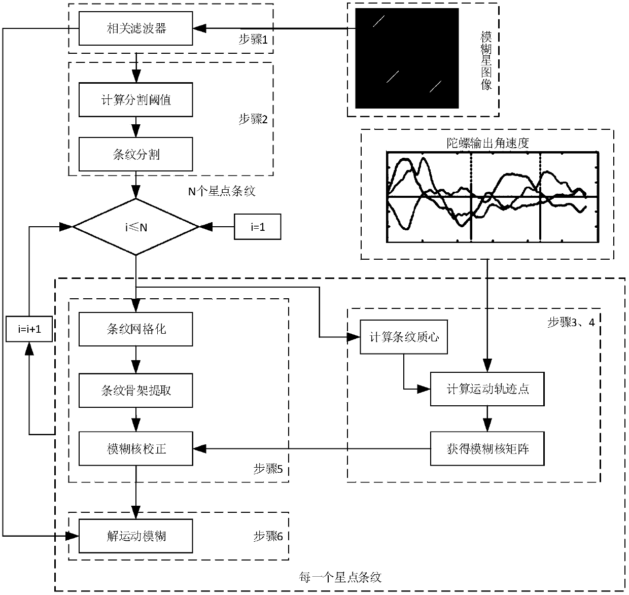
[0037] Specific implementation mode one: combine figure 1 Describe this embodiment, a kind of MEMS gyro-assisted star sensor image solution motion blur method based on this embodiment specific process is:

[0038] Step 1: Acquire the starry sky image I with motion blur through the star sensor origin , adopt the method of spatial filtering to image I of the starry sky with motion blur origin Perform denoising to obtain image I filtered ;

[0039] Step 2, use the threshold method to image I filtered The stripes in are segmented, and the center position coordinates are calculated for each segmented stripe;

[0040] Step 3, read the angular velocity output by the MEMS gyroscope within the exposure time of the star sensor, and use the angular velocity and the center position coordinates of each stripe in step 2 to calculate the position of the star point in image I within the exposure time of the star sensor. filtered According to the trajectory of motion on the fringe, the b...

specific Embodiment approach 2

[0044] Specific embodiment two: the difference between this embodiment and specific embodiment one is: in said step one, gather the starry sky image I with motion blur by star sensor origin , adopt the method of spatial filtering to image I of the starry sky with motion blurorigin Perform denoising to obtain the denoised image I filtered ; The specific process is:

[0045] Step one, construct a two-dimensional Gaussian filter template with a size of 5×5 and σ=1.4:

[0046]

[0047] σ is the standard deviation of the two-dimensional Gaussian filter template;

[0048] Step 1 and 2, by taking the obtained starry sky image I with motion blur origin Perform convolution operation with the filter template to obtain the denoised image, the calculation formula is:

[0049]

[0050] Among them: I origin Acquisition of starry sky images with motion blur for star sensors, I filtered is the denoised image, for the convolution operation.

[0051] Other steps and parameters are...

specific Embodiment approach 3

[0052] Specific embodiment three: the difference between this embodiment and specific embodiment one or two is that: in the step two, the threshold value method is used to image I filtered The stripes in are segmented, the specific process is:

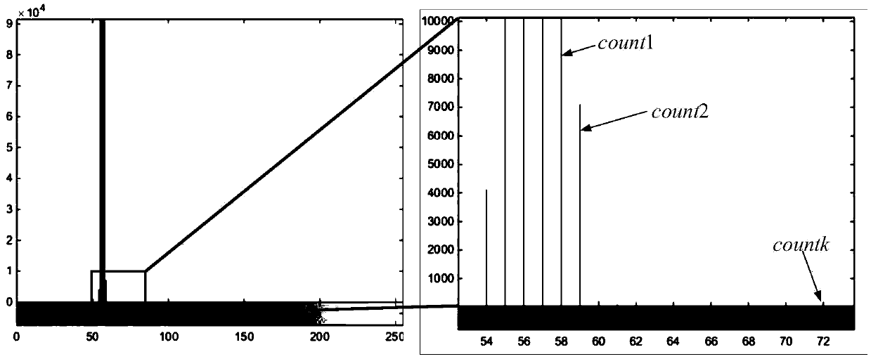
[0053] Step 21, establish a brightness histogram for the image after denoising, count the number of each brightness pixel in the image after denoising, record it as counti, i=0,1,2,...,255, see the histogram figure 2 ;

[0054] Among them, i is the gray level of the image;

[0055] Step 22, calculate the difference d_count between the ratios of two adjacent counti i , the calculation formula is:

[0056]

[0057] if d_count i threshold ;

[0058] Step two and three, build and denoise the image I filtered Binary images of equal size I seg (x img ,y img ), and define the image I seg (x img ,y img ) pixel coordinate system, the origin of which is located in the image I seg (x img ,y img ) The position of the first row a...


PUM


Abstract

The invention relates to a method for solving motion blurring of a star sensor image based on assistance of an MEMS (Microelectro Mechanical System) gyroscope. An objective of the invention is to solve the problem that blurring kernels needed when the motion blurring of the star sensor image is solved cannot be accurately obtained in an existing method. The method comprises the specific process ofI, collecting a star image with motion blurring through a star sensor, and performing denoising to obtain an image; II, segmenting stripes in the image by use of a threshold value method, and calculating a center position coordinate for each segmented stripe; III, calculating a motion trajectory of star points on the image within the exposure time of the star sensor by use of the MEMS gyroscope data, and obtaining a blurring kernel matrix of the stripes according to the motion trajectory; IV, correcting the blurring kernels by use of stripe skeleton characteristics; and V, performing blurringresolution on the image according to the blurring kernels to obtain a final restored image; repeating step III until all star points are recovered. The

Description

technical field [0001] The invention relates to a MEMS gyroscope-assisted star sensor image resolution motion blur method. Background technique [0002] Attitude determination is the premise and basis for spacecraft attitude control, space remote sensing positioning and other tasks. The star sensor is a commonly used attitude sensor on a spacecraft. Through star point extraction and star point centroid position calculation, the position of the star point on the spacecraft is obtained. After the direction vector in the body coordinate system is matched with the navigation star catalog, the attitude of the spacecraft in the inertial coordinate system can be calculated. Typically, star sensors can achieve "second" precision. When the spacecraft maneuvers rapidly, the star sensor moves during the exposure period, which causes the star point to move on the image plane and form stripes in the shape of "smearing", which makes the originally concentrated energy scattered on the str...

Claims


Application Information

Patent Timeline
IPC IPC(8): G06T5/00G06T7/136G06T7/215
CPCG06T7/136G06T7/215G06T2207/10032G06T5/73
Inventor 张世杰王诗强周搏天
Owner HARBIN INST OF TECH
Why Eureka
Try Eureka