Lithium ion battery cathode plate and lithium ion battery
A technology of lithium ion battery and positive electrode sheet, which is applied in the direction of electrode carrier/current collector, secondary battery, secondary battery repair/maintenance, etc., can solve the problems of reduced volume energy density, poor battery cycle performance, and high volume energy density, Achieve the effect of shortening the diffusion distance, increasing the volume energy density, and high energy volume density
- Summary
- Abstract
- Description
- Claims
- Application Information
AI Technical Summary
Problems solved by technology
Method used
Image
Examples
Embodiment 1
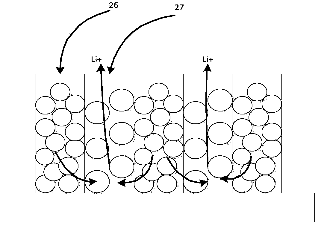
[0041] The lithium-ion battery cathode sheet that embodiment 1 provides is as figure 1 shown. Among them, 26 is the active stripe unit of the first low-porosity positive electrode material, and 27 is the active stripe unit of the second high-porosity positive electrode material.
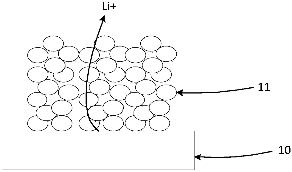
[0042] The cross-sectional view after assembling the positive electrode sheet prepared in Example 1 into a battery is shown in figure 2 As shown, wherein, 10 is a positive electrode current collector, 20 is a positive electrode material layer (including interlaced but not mixed material stripe units), 30 is a separator, 40 is a negative electrode active material layer, and 50 is a negative electrode current collector.
Embodiment 2
[0044] The lithium-ion battery cathode sheet that embodiment 2 provides is as figure 1 shown. Among them, 26 is an active stripe unit of positive electrode material with the same porosity, which does not contain additives, and 27 is an active stripe unit of positive electrode material with the same porosity, which contains additives.
[0045] The cross-sectional view after assembling the positive electrode sheet prepared in Example 2 into a battery is shown in figure 2 As shown, wherein, 10 is a positive electrode current collector, 20 is a positive electrode material layer (including interlaced but not mixed material stripe units), 30 is a separator, 40 is a negative electrode active material layer, and 50 is a negative electrode current collector.
Embodiment 3
[0047] The lithium-ion battery cathode sheet that embodiment 3 provides is as figure 1 shown. Among them, 26 is the active stripe unit of positive electrode material with the same porosity, which contains 2% additive, and 27 is the active stripe unit of positive electrode material with the same porosity, which contains 4% additive.
[0048] The cross-sectional view after assembling the positive electrode sheet prepared in Example 3 into a battery is shown in figure 2 As shown, wherein, 10 is a positive electrode current collector, 20 is a positive electrode material layer (including interlaced but not mixed material stripe units), 30 is a separator, 40 is a negative electrode active material layer, and 50 is a negative electrode current collector.
PUM
| Property | Measurement | Unit |
|---|---|---|
| Width | aaaaa | aaaaa |
Abstract
Description
Claims
Application Information
 - R&D
- Intellectual Property
- Life Sciences
- Materials
- Tech Scout
- Unparalleled Data Quality
- Higher Quality Content
- 60% Fewer Hallucinations
Browse by: Latest US Patents, China's latest patents, Technical Efficacy Thesaurus, Application Domain, Technology Topic, Popular Technical Reports.
© 2025 PatSnap. All rights reserved.Legal|Privacy policy|Modern Slavery Act Transparency Statement|Sitemap|About US| Contact US: help@patsnap.com


