
Silicon-based optical waveguide structure and manufacturing method thereof

A technology for a silicon-based optical waveguide and a manufacturing method, which is applied in the directions of light guides, optics, optical components, etc., can solve the problems of difficult manufacturing processes and high costs of silicon-based optical waveguide structures, and achieve reduced equipment and process costs, low manufacturing costs, and improved performance effect

Active Publication Date: 2020-06-05
SHANGHAI IND U TECH RES INST
View PDF13 Cites 0 Cited by
  • Summary
  • Abstract
  • Description
  • Claims
  • Application Information

AI Technical Summary

Problems solved by technology

[0006] In view of the above-mentioned shortcomings of the prior art, the object of the present invention is to provide a silicon-based optical waveguide structure and its manufacturing method, which are used to solve the problems of difficult manufacturing process and high cost of the silicon-based optical waveguide structure in the prior art

Method used


Image

  • Silicon-based optical waveguide structure and manufacturing method thereof
  • Silicon-based optical waveguide structure and manufacturing method thereof
  • Silicon-based optical waveguide structure and manufacturing method thereof

Examples


Embodiment Construction

[0038] Embodiments of the present invention are described below through specific examples, and those skilled in the art can easily understand other advantages and effects of the present invention from the content disclosed in this specification. The present invention can also be implemented or applied through other different specific implementation modes, and various modifications or changes can be made to the details in this specification based on different viewpoints and applications without departing from the spirit of the present invention.

[0039] see Figure 2 to Figure 7 . It should be noted that the diagrams provided in this embodiment are only schematically illustrating the basic idea of ​​the present invention, so that only the components related to the present invention are shown in the diagrams rather than the number, shape and shape of the components in actual implementation. Dimensional drawing, the type, quantity and proportion of each component can be changed...


PUM


Abstract

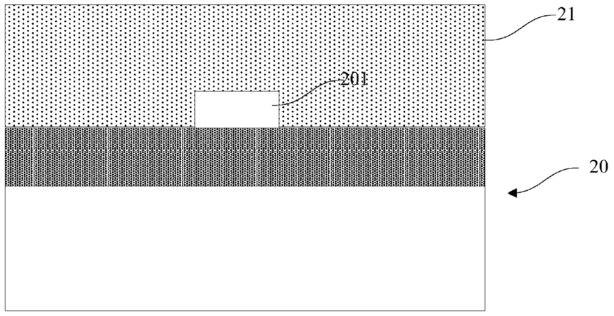
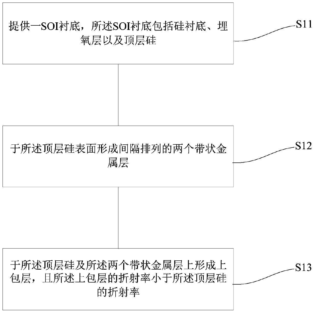
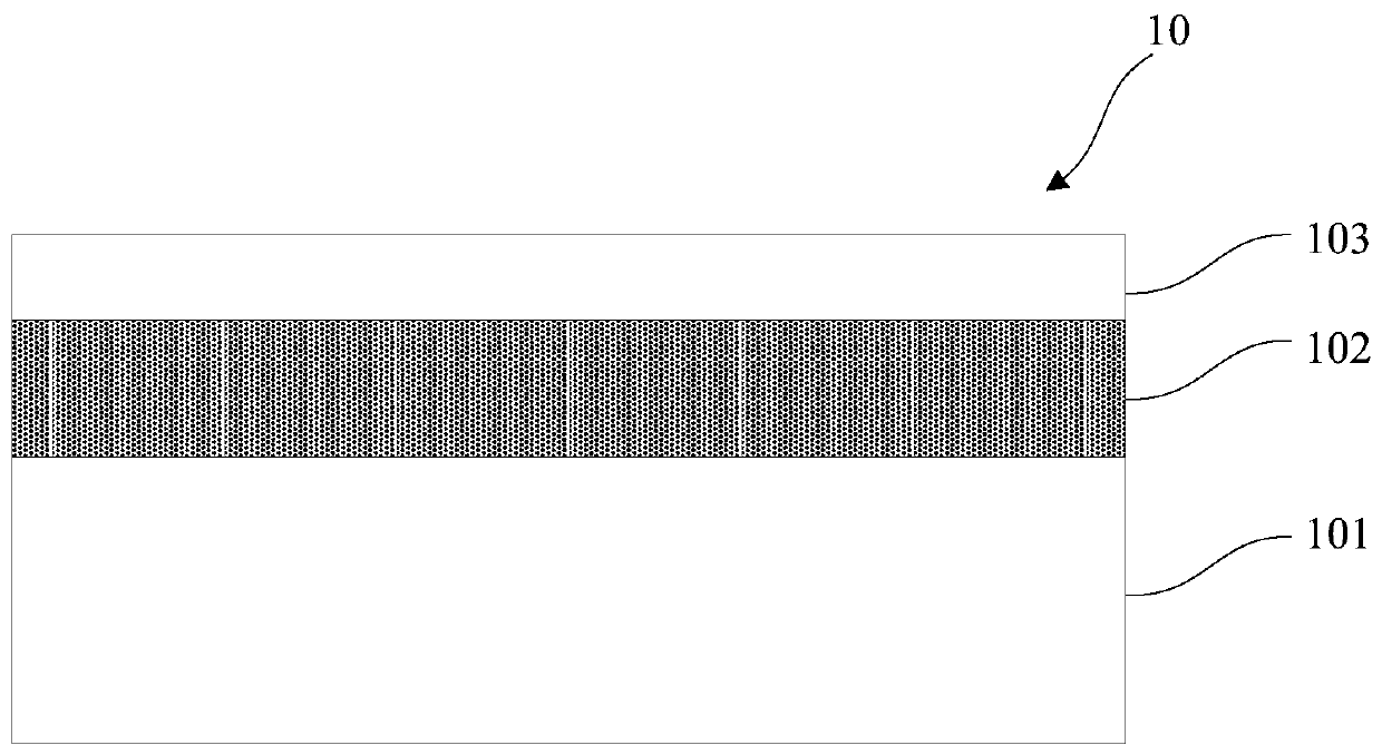
The invention provides a silicon-based optical waveguide structure and a manufacturing method thereof. The manufacturing method comprises the steps that a SOI substrate is provided, wherein the SOI substrate includes a silicon substrate, a buried oxide layer and top silicon; two spaced strip metal layers are formed on surface of the top silicon; and an upper wrapping layer is formed on the top silicon and the two strip metal layers, and the refractive index of the upper wrapping layer is less than that of the top silicon. The high-refractive-index top silicon is clamped between the low-refractive-index buried oxide layer and the upper wrapping layer in the longitudinal direction so as to form longitudinal light field limit; and the strip metal layer region has strong light absorption in the transverse direction and the equivalent refractive index is less than that of the region between the two strip metal layers so as to form the transverse light field limit, and finally realize the longitudinal and transverse light field limit and form the silicon-based optical waveguide structure and effectively enhance the performance of the optical waveguide. Dry etching of the top silicon material is not needed so that the process difficulty can be greatly reduced and the equipment and process cost can be reduced.

Description

technical field [0001] The invention belongs to the field of semiconductors and optoelectronic integration, and in particular relates to a silicon-based optical waveguide structure and a manufacturing method thereof. Background technique [0002] With the continuous improvement of people's requirements for information transmission and processing speed and the advent of the era of multi-core computing, metal-based electrical interconnections will become a development bottleneck due to defects such as overheating, delay, and electronic interference. The use of optical interconnection to replace electrical interconnection can effectively solve this problem. In the specific implementation of optical interconnection, silicon-based optical interconnection has become the first choice due to its unparalleled cost and technical advantages. Silicon-based optical interconnection can not only give full play to the advantages of fast optical interconnection speed, large bandwidth, anti-...

Claims


Application Information

Patent Timeline
Patent Type & Authority Patents(China)
IPC IPC(8): G02B6/122G02B6/136
CPCG02B6/122G02B6/136
Inventor 盛振武爱民仇超赵瑛璇高腾甘甫烷王曦
Owner SHANGHAI IND U TECH RES INST
Learn More