Radar directional diagram measurement method based on parabolic antenna

A technology of parabolic antenna and measurement method, which is applied in the direction of educational appliances, instruments, teaching aids, etc., can solve the problems of abstract concept of antenna, difficult to understand, many students, and less radar equipment, etc. It is easy to meet the test conditions, the workload is small, and the measurement The effect of low site requirements

Inactive Publication Date: 2018-11-23
PLA OF CHINA AIR FORCE EARLY WARNING ACADEMY LEIDA SERGEANT SCHOOL
View PDF8 Cites 4 Cited by
  • Summary
  • Abstract
  • Description
  • Claims
  • Application Information

AI Technical Summary

Problems solved by technology

Realize multi-person teaching at the same time, solve the problems of less radar equipment, more students, and abstract concepts of antennas that are difficult to understand

Method used


Image

  • Radar directional diagram measurement method based on parabolic antenna
  • Radar directional diagram measurement method based on parabolic antenna
  • Radar directional diagram measurement method based on parabolic antenna

Examples


Embodiment Construction

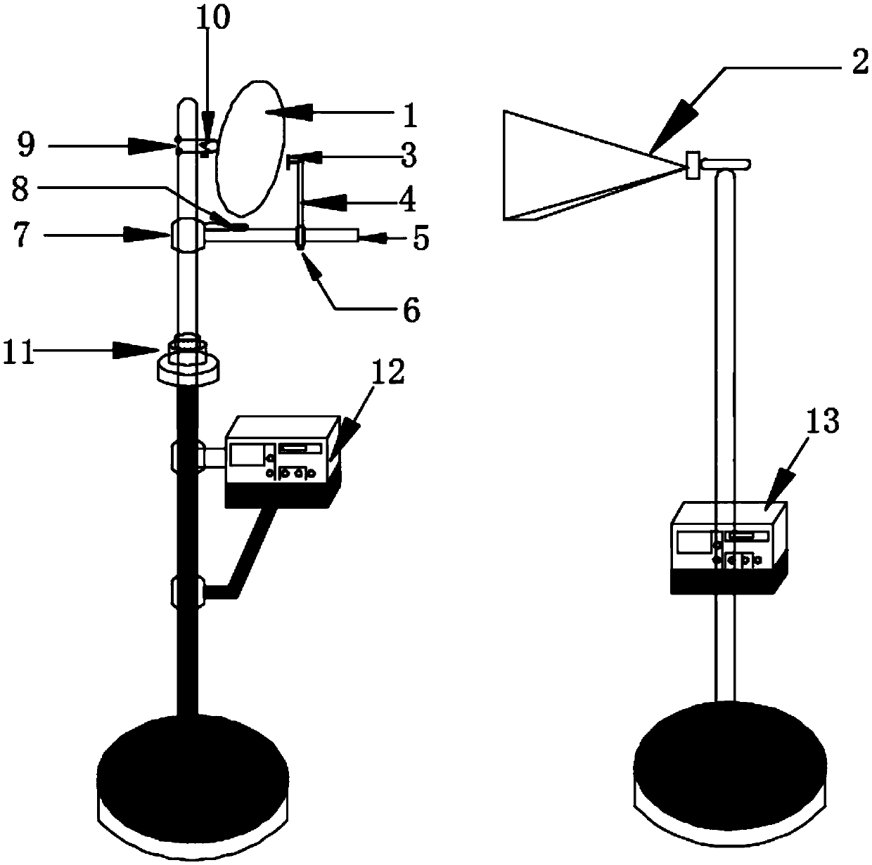
[0032] Below in conjunction with accompanying drawing, the present invention is illustrated,

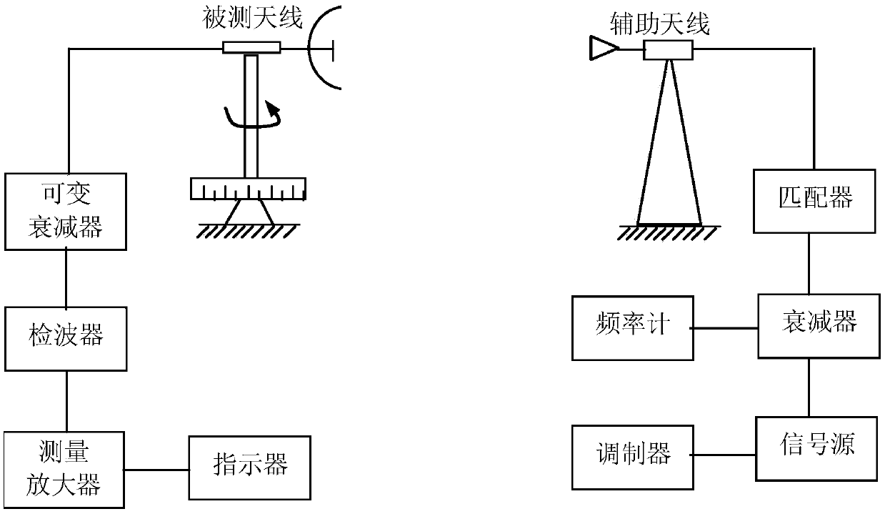
[0033] The basic principle of the invention is the theory of electromagnetic wave free space propagation. The power expression of the signal received by the antenna under test is:

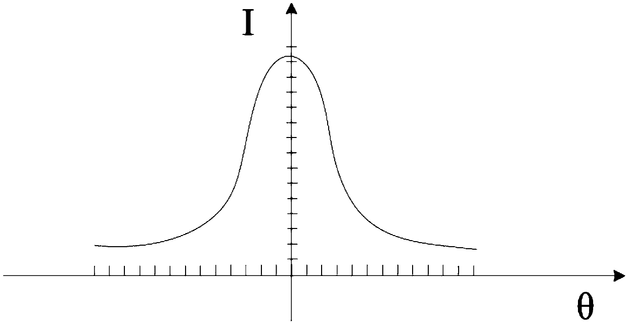
[0034] Among them, P 1 is the received power of the antenna under test, P 0 is the equivalent isotropic radiated power of transmitting antenna 2, G 0 is the gain of transmitting antenna 2, G 1 is the measured antenna gain, λ is the signal source wavelength, is the normalized directivity function of the measured antenna field strength, where θ is the azimuth angle, is the pitch angle, r is the propagation distance from the transmitting antenna 2 to the antenna under test, and L is the atmospheric loss from the transmitting signal to the antenna under test.

[0035] The measurement needs to meet the far-field conditions: (the distance between the auxiliary antenna and the main antenna r>2D 2 / λ, ...


PUM


Abstract

The invention discloses a radar directional diagram measurement method based on a parabolic antenna, and the method comprises the steps: taking an auxiliary antenna for measurement as a transmitting antenna, and taking a measured parabolic antenna as a receiving antenna; adjusting a feed source of the parabolic antenna to be at a positive focus position through an auxiliary adjustment device, andlocking the relative position; rotating the parabolic antenna, recording the azimuth angle of the parabolic antenna as a measurement starting angle when the deviation of the pointer of the frequency-selective amplifier is the maximum; continuing to adjust the antenna till the frequency-selective amplifier points to 0, and determining a measurement end angle; reading the indicated values of the frequency-selective amplifier at the intervals of delta(theta) from the measurement start angle to the measurement end angle, taking the direction angle of the parabolic antenna and the indicated valuesof the frequency-selective amplifier as the parameters of all points, drawing the position of each point in the rectangular coordinate system and the polar coordinate system, and connecting all pointsinto a curve to obtain a corresponding horizontal directional diagram of the parabolic antenna. The method is simple in measurement process, is reliable in measurement result, and is especially suitable for the demonstrative testing.

Description

technical field [0001] The invention belongs to the field of radar antenna pattern measurement, and relates to a radar antenna pattern measurement method, in particular to a radar pattern measurement method based on a parabolic antenna. Background technique [0002] The antenna pattern characterizes the distribution of antenna radiation energy in space, and reflects the performance index and working status of the antenna. By measuring the antenna pattern, it is possible to determine the important antenna parameters such as the antenna's directional coefficient, gain, half-power beam width, and sidelobe level, and analyze the radiation characteristics of the antenna, which can be used for debugging, installation, maintenance, and overhaul of the antenna during use. Provide analysis data to determine whether the antenna performance indicators meet the requirements and whether the antenna is faulty. [0003] In order to better carry out teaching and assist students to better g...

Claims


Application Information

Patent Timeline
Patent Type & Authority Applications(China)
IPC IPC(8): G09B19/00
CPCG09B19/00
Inventor 李琼李延辉张朝伟胡晓琴简涛杨建华
Owner PLA OF CHINA AIR FORCE EARLY WARNING ACADEMY LEIDA SERGEANT SCHOOL
Why Eureka
Try Eureka