
ICF (inertial confinement fusion) cryogenic target device and ICF shielding cover opening speed optimization method

A technology for freezing targets and shielding covers, which is applied in the fields of nuclear reactors, nuclear power generation, climate sustainability, etc., can solve the problems of high failure probability, ignition uncertainty, and high cost, so as to improve the probability of one-time success and improve ignition success rate, the effect of improving the success rate

Inactive Publication Date: 2018-11-23
陈鹏玮
View PDF5 Cites 8 Cited by
  • Summary
  • Abstract
  • Description
  • Claims
  • Application Information

AI Technical Summary

Problems solved by technology

When the shield is opened, the radiation from the external environment is directly projected into the black cavity, which significantly increases the heating inside the black cavity, the radiation intensity and the convective heat transfer in the black cavity increase, which intensifies the temperature field disturbance of the target pellet, which has a great impact on the ignition process
[0004] The cost of the original test method for passing experiments is extremely high, and different experiments are required for different structures, and due to the uncertainty of ignition, the probability of failure is relatively high

Method used


Image

  • ICF (inertial confinement fusion) cryogenic target device and ICF shielding cover opening speed optimization method
  • ICF (inertial confinement fusion) cryogenic target device and ICF shielding cover opening speed optimization method
  • ICF (inertial confinement fusion) cryogenic target device and ICF shielding cover opening speed optimization method

Examples


Embodiment 1

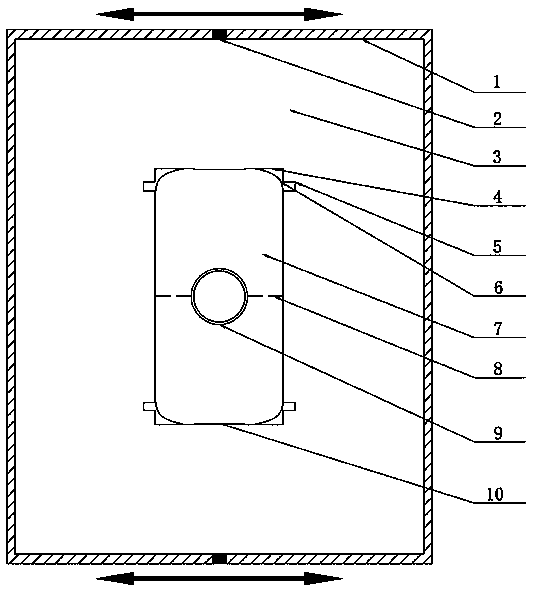
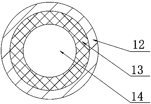
[0025] Embodiment 1: Reference figure 1 , the gold cavity 6 containing the frozen target pellet 9 is located in the thermomechanical structure 4, the laser entrance (LEH) 10 is the window for the laser incident during ignition, the inner diameter of the gold cavity 6 is 5.44mm, the inner height is 10mm, and the thickness is 10μm. The outer side of the gold cavity 6 is a thermomechanical structure 4 made of high-purity aluminum, the material of the outermost shell 12 of the frozen target pellet 9 is hydrocarbon polymer, the outer diameter of the frozen target pellet 9 is 1.16 mm, and the intermediate fuel ice layer 13 is 63 μm thick In the DT ice layer, the innermost fuel gas 14 is DT gas. The frozen target pellet 9 is supported at the center of the structure by a support film 7 made of a polymer film with a thickness of about 0.1 μm. There is a vacuum area 3 between the outer heat radiation shield 1 and the thermomechanical structure 4 , and the heat radiation shield 1 is com...

Embodiment 2

[0032] Embodiment 2: Reference figure 1 , the gold cavity 6 containing the frozen target pellet 9 is located in the thermomechanical structure 4, the laser entrance (LEH) 10 is the window for the laser incident during ignition, the inner diameter of the gold cavity 6 is 5.44mm, the inner height is 10mm, and the thickness is 10μm. The outer side of the gold cavity 6 is a thermomechanical structure 4 made of high-purity aluminum, the material of the outermost shell 12 of the frozen target pellet 9 is hydrocarbon polymer, the outer diameter of the frozen target pellet 9 is 1.16 mm, and the intermediate fuel ice layer 13 is 63 μm thick In the DT ice layer, the innermost fuel gas 14 is DT gas. The frozen target pellet 9 is supported at the center of the structure by a support film 7 made of a polymer film with a thickness of about 0.1 μm. There is a vacuum between the outer heat radiation shield 1 and the thermomechanical structure 4 , and the heat radiation shield 1 is composed o...

Embodiment 3

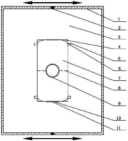
[0039] Embodiment three: reference figure 2 , the gold cavity 6 containing the frozen target pellet 9 is located in the thermomechanical structure 4, the laser entrance (LEH) 10 is the window for the laser incident during ignition, and the absorption rate is 0.9, and there is a storm window 11 outside the laser entrance (LEH) 10, Its absorption rate is 0.9, the inner diameter of the gold cavity 6 is 5.44 mm, the inner height is 10 mm, and the thickness is 10 μm. The outer side of the gold cavity 6 is a thermomechanical structure 4 made of high-purity aluminum, the material of the outermost shell 12 of the frozen target pellet 9 is hydrocarbon polymer, the outer diameter of the frozen target pellet 9 is 1.16 mm, and the intermediate fuel ice layer 13 is 63 μm thick In the DT ice layer, the innermost fuel gas 14 is DT gas. The frozen target pellet 9 is supported at the center of the structure by a support film 7 made of a polymer film with a thickness of about 0.1 μm. There i...


PUM

PropertyMeasurementUnit
The inside diameter ofaaaaaaaaaa
Internal heightaaaaaaaaaa
Thicknessaaaaaaaaaa

Abstract

The invention discloses an ICF (inertial confinement fusion) cryogenic target device and an ICF shielding cover opening speed optimization method. The ICF cryogenic target device comprises a thermal radiation shielding cover; a vacuum region is defined in the thermal radiation shielding cover; a thermal mechanical structure is arranged in the vacuum region; the outer sides of the upper part and lower part of the thermal mechanical structure are provided with two cold rings respectively; a gold cavity is closely attached to the inside of the thermal mechanical structure; the gold cavity is filled with a filling gas; a cryogenic target pellet is fixed to the center of the gold cavity through a supporting film; and the thermal radiation shielding cover is composed of two detachable parts which are connected through a shielding cover connection structure. The ICF shielding cover opening speed optimization method of the invention includes the following steps that: the radiation temperatureof the thermal radiation shielding cover is determined; a model is established according to the radiation temperature and the specific condition of the cryogenic target; the opening mode of the thermal radiation shielding cover is determined; and different shielding cover opening speeds are provided, and an optimized opening speed and corresponding time are obtained.

Description

technical field [0001] The invention belongs to the field of inertial confinement fusion (ICF) target ignition, and in particular relates to an ICF freezing target device and an optimal method for opening speed of an ICF shielding cover. Background technique [0002] In inertial confinement fusion (ICF), the frozen target has higher initial fuel density and lower shock wave preheating sensitivity, which can reduce the energy required for compressing the target pellet. Compared with the non-frozen target, the sub-yield is significantly increased. Therefore, the frozen target has become the first choice for ICF ignition in the world. In order to suppress the growth of Rayleigh-Taylor instability, the thickness uniformity of the deuterium-tritium (DT) layer in the cryo target must be greater than 99% and the root mean square of the inner surface roughness must be less than 1 μm, corresponding to a surface temperature difference of less than 0.1mK. Its driving source can be a l...

Claims


Application Information

Patent Timeline
IPC IPC(8): G21B1/19
CPCG21B1/19Y02E30/10
Inventor 陈鹏玮寇家静
Owner 陈鹏玮
Learn More