
Double-reflecting surface antenna with special shape guided wave dielectric rod feeding

A special shape, double reflector technology, applied in antenna, antenna grounding switch structure connection, circuit, etc., can solve the problem of reducing antenna efficiency, high cross-plan and beam tilt, affecting high-order mode sidelobe level and cross-polarization, etc. problem, to achieve the effect of symmetrical structure, small size and low impedance loss

Inactive Publication Date: 2018-11-23
NANJING UNIV OF SCI & TECH
View PDF6 Cites 5 Cited by
  • Summary
  • Abstract
  • Description
  • Claims
  • Application Information

AI Technical Summary

Problems solved by technology

[0003] Complementary focus parabolic reflector antenna has many advantages, such as high isolation between antenna and feed, low sidelobe, but this structure also has its disadvantages: high cross-plan and beam tilt;
[0004] The main focus parabolic reflector antenna has more advantages: cheap, high performance, easy maintenance and easy assembly, however, this symmetrical structure will seriously affect the side lobe level and cross polarization of high order modes, thus reducing the efficiency of the antenna

Method used


Image

  • Double-reflecting surface antenna with special shape guided wave dielectric rod feeding
  • Double-reflecting surface antenna with special shape guided wave dielectric rod feeding
  • Double-reflecting surface antenna with special shape guided wave dielectric rod feeding

Examples


Embodiment

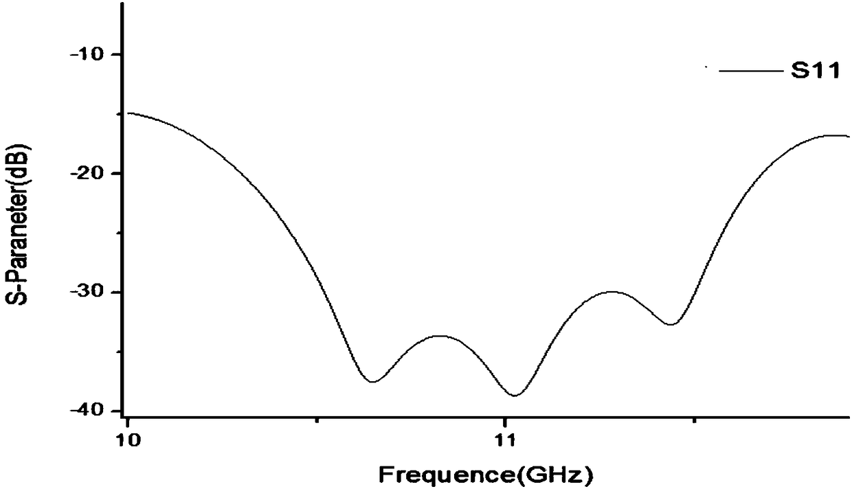
[0033] Before giving the entire parabolic reflector antenna, we give the design and optimization of the matching feed: the antenna works at 10.40GHz to 11.33GHz.

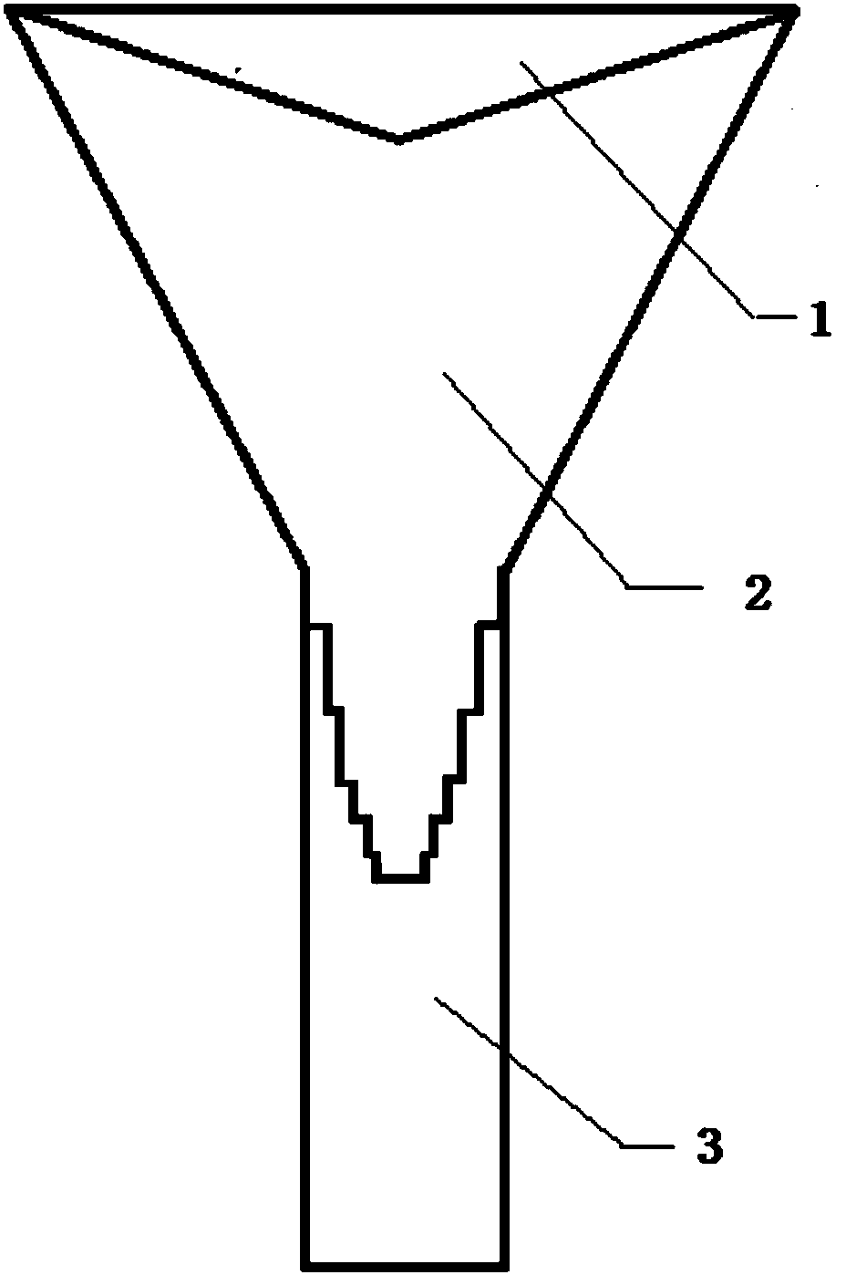
[0034] In the example design made, the size of the selected double reflector antenna is 600mm in diameter, the operating frequency of the double reflector antenna is 10.40GHz-11.33GHz, the inner diameter of the circular waveguide is 12.5mm, the length is 89mm, and the secondary reflector Dimensions: the diameter of the circular platform is 100mm, and the height is 17.5mm; its center is located near the focus of the paraboloid. By adjusting the value of the distance t between the vertex of the parabolic reflector 4 and the conical secondary reflector 1 , the phase center of the feed can be moved to the focal point of the paraboloid reflector 4 .

[0035] The ground diameter of the dielectric circular table is 100mm and the upper table diameter is 12.5mm. The height of the circular table just connects the circular wav...


PUM


Abstract

The invention discloses a double-reflecting surface antenna with a special shape guided wave dielectric rod feeding. The antenna includes a circular waveguide, a guided-wave dielectric rod, a taperedsecondary reflecting surface, a parabolic reflecting surface, and a metal ring, wherein the guided-wave dielectric rod is located between the tapered secondary reflecting surface and the circular waveguide, the guided-wave dielectric rod is inserted to the inner cavity of the circular waveguide, the guided-wave dielectric rod located in the inner cavity portion of the circular waveguide is dividedinto a plurality of coaxial circular tables, and the radius of the circular tables decreases progressively in a direction from the tapered secondary reflecting surface to the parabolic reflecting surface; the circular waveguide is located at the center of the main reflecting surface, the axis of the circular waveguide and the diameter of the antenna point to the same direction, and a microwave signal is introduced by the circular waveguide, sent to the tapered secondary reflecting surface by the guided-wave dielectric rod and reflected to the parabolic reflecting surface, and finally emittedby the parabolic reflecting surface in parallel. The invention effectively improves the reflection coefficient S11 of the double-reflecting surface antenna, is capable of effectively suppressing the cross polarization, reducing the ohmic loss, reducing the sidelobe level, and improving the radiation efficiency, and is symmetrical in structure, compact and simple, and easy to implement.

Description

technical field [0001] The invention belongs to the technical field of antennas, in particular to a dual-reflection-surface antenna fed by a special-shaped waveguide dielectric rod. Background technique [0002] Dual-reflector antennas have been the focus of research in many practical applications, such as satellite communications, radio frequency telescopes, microwave transmission and remote sensing systems. The shape of the reflective surface has four typical forms: paraboloid, ellipse, cylinder, and sphere. Paraboloid is the most common reflective surface structure, in which the main focus and complementary focus are the main feeding positions: [0003] Complementary focus parabolic reflector antenna has many advantages, such as high isolation between antenna and feed, low sidelobe, but this structure also has its disadvantages: high cross-plan and beam tilt; [0004] The main focus parabolic reflector antenna has more advantages: cheap, high performance, easy maintenan...

Claims


Application Information

Patent Timeline
Patent Type & Authority Applications(China)
IPC IPC(8): H01Q19/19H01Q13/02H01Q1/50
CPCH01Q19/19H01Q1/50H01Q13/02
Inventor 张金栋汤普祥冯敏吴翠翠汪书阁周雅莉姚祺陈峤羽
Owner NANJING UNIV OF SCI & TECH
Learn More