Optimal torque angle control system of built-in permanent magnet synchronous motor

A technology of permanent magnet synchronous motor and control system, applied in control system, vector control system, motor generator control and other directions, can solve problems such as poor control accuracy, and achieve the effect of simple control method, strong robustness and dynamic performance

Active Publication Date: 2018-11-23
JIANGSU UNIV
View PDF6 Cites 4 Cited by
  • Summary
  • Abstract
  • Description
  • Claims
  • Application Information

AI Technical Summary

Problems solved by technology

[0014] The purpose of the present invention is to solve the problem of poor control accuracy of the existing permanent magnet synchronous motor in the use of the maximum torque current ratio control strategy, and to propose a built-in permanent magnet synchro

Method used


Image

  • Optimal torque angle control system of built-in permanent magnet synchronous motor
  • Optimal torque angle control system of built-in permanent magnet synchronous motor
  • Optimal torque angle control system of built-in permanent magnet synchronous motor

Examples


Embodiment Construction

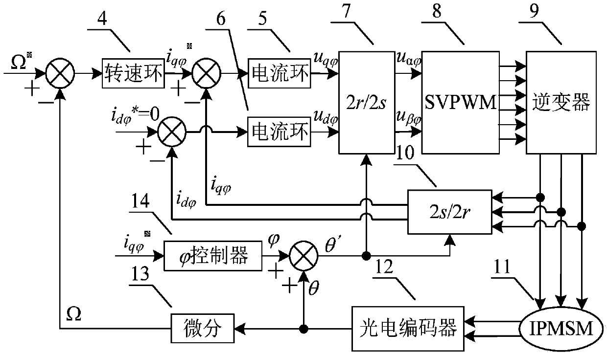
[0034] see figure 2 , the present invention uses the photoelectric encoder module 12 to collect the rotor position angle θ of the built-in permanent magnet synchronous motor 11 . The output terminal of the photoelectric encoder module 12 is connected to the input terminal of the differential module 13 , and the rotor position angle θ is calculated by the differential module 13 to obtain the motor speed Ω. Compare the motor speed Ω with the given speed Ω * For comparison, the comparison difference is input to the speed loop control module 4, and the given current is obtained through the speed loop control module 4 Output connection of speed loop control module 4 The input terminal of the controller 14, the given current input to In the controller 14. given current go through The controller 14 obtains and outputs the optimum torque angle best torque angle Add the output rotor position angle θ of the photoelectric encoder module 12 to obtain the new rotor positi...


PUM


Abstract

The invention discloses an optimal torque angle control system of a built-in permanent magnet synchronous motor. A difference value obtained after comparison of a motor rotating speed and a given rotating speed is input to a rotating speed loop control module to obtain given current i<q phi><*>, the given current i<q phi><*> is input to a phi controller, the phi controller outputs an optimal torque angle phi, a new rotor position angle theta' is obtained by adding the optimal torque angle phi and a motor rotor position angle, and the new rotor position angle theta' is input to a 2r/2s coordinate transformation module and a 2s/2r coordinate transformation module. The phi controller is composed of a band-pass filter, a low-pass filter and an integral controller, a high-frequency signal is input to the phi controller, and then the given current i<q phi><*> contains a high-frequency signal delta<phi>. The optimal torque angle is obtained by inputting the high-frequency signal under the control condition that d-axis given current is zero, the optimal torque angle is compensated to the position angle to obtain maximum electromagnetic torque without the influence of operation conditions and motor parameters, and high robustness and dynamic performance are achieved.

Description

technical field [0001] The invention belongs to the field of motor control, and in particular relates to a control system for an optimal torque angle of an internal permanent magnet synchronous motor (IPMSM), which is particularly suitable for application occasions such as permanent magnet synchronous motors of electric vehicles that require quick start. Background technique [0002] Vehicle drive motor is one of the key executive components of electric vehicles, and its driving performance directly affects the overall performance of electric vehicles. Built-in permanent magnet synchronous motors are widely used in the field of electric vehicles due to their advantages such as high efficiency, high torque density, and high power density. Due to the unequal inductance of the d and q axes of the built-in permanent magnet synchronous motor, the output electromagnetic torque includes two parts: excitation torque and reluctance torque. Conventional d-axis current i d = 0 contro...

Claims


Application Information

Patent Timeline
IPC IPC(8): H02P21/20
CPCH02P21/20
Inventor 朱孝勇刘天奇左月飞
Owner JIANGSU UNIV
Why Eureka
Try Eureka