High energy beam welding quality determining method, quality determining device using determining method, and welding management system using determining method

A high-energy beam and judgment method technology, which is applied in the direction of charging system, welding equipment, laser welding equipment, etc., to achieve the effect of improving judgment accuracy and improving manufacturing efficiency

Inactive Publication Date: 2018-11-23
HITACHI AUTOMOTIVE SYST LTD
View PDF8 Cites 11 Cited by
  • Summary
  • Abstract
  • Description
  • Claims
  • Application Information

AI Technical Summary

Problems solved by technology

It is assumed that welding problems can be determined by applying the above method to laser welding, and welding defects can be prevented by making welding quality uniform

Method used


Image

  • High energy beam welding quality determining method, quality determining device using determining method, and welding management system using determining method
  • High energy beam welding quality determining method, quality determining device using determining method, and welding management system using determining method
  • High energy beam welding quality determining method, quality determining device using determining method, and welding management system using determining method

Examples


no. 1 example

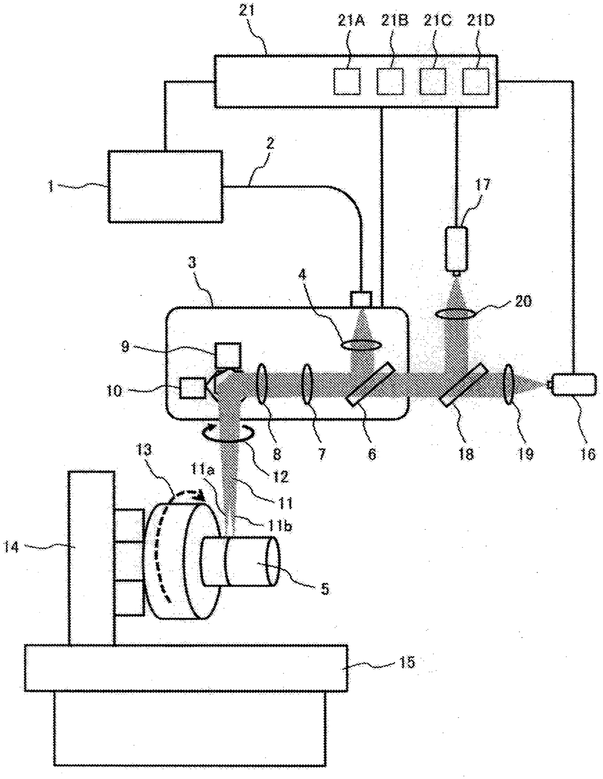
[0050] figure 1 is a schematic diagram of the laser welding apparatus of the first embodiment.

[0051] 11 represents a laser, 16 represents a camera, and 17 represents a welding light sensor. 1 indicates a laser oscillator, 2 indicates an optical fiber for laser, 3 indicates a Galvana scanner (processing head), 4 indicates a collimator lens that expands the beam width in a Galvana scanner, 5 indicates a welding object, and 6 indicates the The light emitted from the welding object 5 is transmitted to the camera 16 and the welding optical sensor 17 through a partial wavelength reflector, 7 represents the Z-axis control lens for controlling the Z-axis position of the laser 11, and 8 represents the laser that makes the beam width wider 11 focuses on the objective lens of the welding object 5, 9 represents the X-axis control Galvano mirror for controlling the X-axis position of the laser 11, 10 represents the Y-axis control Galvano mirror for controlling the Y-axis position of th...

no. 2 example

[0109] Figure 12 is a flowchart of the feedback control of the second embodiment. It should be noted that the same symbols as those in the first embodiment are used for the same or the same structural components as those in the first embodiment.

[0110] This second embodiment can be implemented using the same laser welding device as the first embodiment. In addition, the predicted value of the depth of penetration is obtained by the method described in the first embodiment. That is, it has a structure different from that of the first embodiment in the flow of feedback control.

[0111] In step 61 , when the welding time exceeds the start time Ts90 of the feedback control section 90 , the flow of the feedback control starts. In step 62, it is determined whether or not the predicted value of penetration is within the upper and lower limits (SH3, SH2). In the case of YES, the welding condition is maintained in step 63 , and it is determined in step 64 whether or not the wel...

no. 3 example

[0118] Figure 13 is a schematic diagram of the laser welding apparatus of the third embodiment.

[0119] The same symbols as in the first embodiment are used for the same structural components as in the first embodiment. For the same structural components as those of the first embodiment, explanations are omitted.

[0120] In the present third embodiment, the welding target 5A is different from the first embodiment. Others are the same as the first embodiment. The welding object 5A is a fuel injection fitting. The welding joint of the welding object 5A is a lap welding structure.

[0121] In the present third embodiment, although lap welding is applied, the weld joint structure is not limited thereto. In addition, in the third embodiment, the type of laser to be used, the material to be welded, and the laser welding conditions are not limited thereto.

[0122] In addition, the feedback control described in the second embodiment can also be applied in this third embodime...


PUM

PropertyMeasurementUnit
wavelengthaaaaaaaaaa

Abstract

The present invention can improve accuracy of determining a welding quality or accuracy of maintaining, through feedback, a fixed welding quality in high energy beam welding, and thereby, improves themanufacturing efficiency, that is, the yield of welded articles. The present invention is characterized in that: an image of a molten pool is acquired by a camera; the width, length, and area of themolten pool are acquired by image processing; reflected light, plasma, and thermal radiation light are further acquired by an optical sensor; a weld penetration depth is predicted with high accuracy by multiple regression analysis using signals and using certain signals having interaction therebetween among the signals, and thus, a welding quality is determined with high accuracy; and beam outputand a focal position are also predicted, the beam output and the focal point are maintained at appropriate values by feedback control of the beam output and the focal position, and thus, the welding quality is maintained at a fixed level.

Description

technical field [0001] The invention relates to high energy beam welding, in particular to a high energy beam welding method for motor vehicle accessories. Background technique [0002] High-energy beam welding can perform deep penetration welding, and can weld more accurately and at a higher speed than conventional arc welding, so its use has been expanding in recent years. The reason why deep penetration welding is possible is that, for example, a high-energy beam has a higher energy density than arc welding or the like. The metal irradiated by the high-energy beam with high energy density is instantly melted and evaporated. Due to the high reaction force of this vaporization, the melting portion is pressed down, forming a space called a keyhole. The high-energy beam passes through the keyhole and is able to reach the interior of the material, thus achieving a deep penetration weld. In high energy beam welding, conventionally, attention has been paid to management of we...

Claims


Application Information

Patent Timeline
Patent Type & Authority Applications(China)
IPC IPC(8): B23K26/21B23K26/00B23K26/03B23K26/046B23K26/08F02M59/44F02M61/16
CPCB23K26/00B23K26/03B23K26/046B23K26/08F02M59/44F02M61/16B23K26/21B23K26/032B23K31/125B23K9/0956B23K10/02
Inventor 一户诚之宫城雅德黑木达郎张旭东井上亮
Owner HITACHI AUTOMOTIVE SYST LTD
Why Eureka
Try Eureka