[0022] The technical solutions in the embodiments of the present invention will be clearly and completely described below with reference to the accompanying drawings in the embodiments of the present invention. Obviously, the described embodiments are only a part of the embodiments of the present invention, but not all of the embodiments. Based on the embodiments of the present invention, all other embodiments obtained by those of ordinary skill in the art without creative efforts shall fall within the protection scope of the present invention.
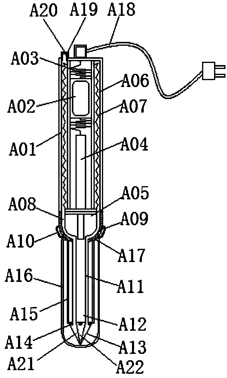
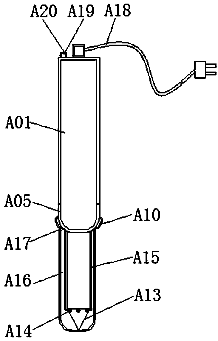
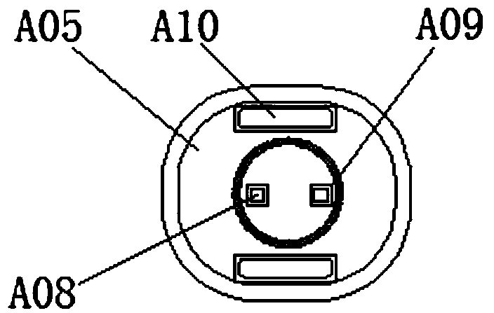
[0023] see Figure 1-3 , an integrated circuit board convenient hairspring fixing device, including fixing device main body A01, rechargeable battery A02, spring A03, conductor A04, fixed shaft A05, placement channel A06, tin bronze A07, first flow channel A08, gear A09, lighting lamp A10, second flow channel A11, first current channel A12, equipment head A13, fixing thread A14, chute A15, protective cover A16, fixing buckle A17, charging cable A18, feed port A19, rotary feed port cover A20 , the third current channel A21 and the second current channel A22, a rechargeable battery A02 is installed inside the upper end of the main body A01 of the fixed device, and the upper and lower ends of the rechargeable battery A02 are connected with a spring A03, the connection between the spring A03 and the rechargeable battery A02 The method is active connection, and a fixed structure is formed between the spring A03 and the conductor A04, which can play a role of stability and control to a certain extent when the main body A01 of the fixed device is operated, and can fix the rechargeable battery A02 to keep the current flow. It is stable, and the rechargeable battery A02 can continue to operate if the power is cut off when the rechargeable battery A02 is charged. The lower end of the spring A03 is connected with the conductor A04, and the lower end of the conductor A04 is fixed with a fixed shaft A05, the main body of the fixed device A01. The inner walls of the left and right sides are provided with placement channels A06, and the interior of the placement channels A06 is provided with tin bronze A07. An integrated structure is formed between the placement channels A06 and the main body A01 of the fixing device, and the placement channels A06 are symmetrically arranged with the conductor A04 as the center. , the tin bronze A07 can be placed inside the placement channel A06. When a route is soldered to the main body A01 of the fixed device, the tin bronze A07 can be welded into the interior of the route immediately. The inner walls of the left and right sides of the fixed shaft A05 are provided with first flow channels. A08, and the gear A09 is arranged on the outside of the first flow channel A08, the lighting lamp A10 is installed around the outside of the fixed rotating shaft A05, the fixed rotating shaft A05 and the lighting lamp A10 form an engaging structure, and the fixed rotating shaft A05 and the fixed device main body A01 A rotating structure is formed between them, and the rotation range is 0-360°. The fixed shaft A05 can be rotated by hand, and the flow of the tin bronze A07 can be stopped, so as to facilitate the connection of the current and facilitate the operation of the equipment head A13. Fix the equipment main body A01 The inner left and right side walls of the lower end are provided with a second flow channel A11, and the inner middle position of the lower end of the main body A01 of the fixing device is provided with a first current channel A12. A14 is installed on the upper end of the equipment head A13. The equipment head A13 forms a threaded structure between the fixing thread A14 and the fixing equipment body A01, and an integrated structure is formed between the equipment head A13 and the third flow channel A21, and the lower end of the fixing equipment body A01 is formed. The left and right sides of the outer wall are provided with chute A15, and the protective sleeve A16 is arranged on the periphery of the lower end of the main body A01 of the fixing device, and the top left and right sides of the protective sleeve A16 are provided with fixed inner parts. Buckle A17, a sliding structure is formed between the chute A15 and the fixing buckle A17, and an integrated structure is formed between the chute A15 and the main body A01 of the fixing device, which can facilitate the protection sleeve A16 to protect the lower end of the main body A01 of the fixing device, which can be fixed by fixing The buckle A17 fixes the protective cover A16 to prevent it from falling. The charging cable A18 is set at the top of the main body A01 of the fixed device. The left side of the charging cable A18 is provided with a feeding port A19, and the top of the feeding port A19 is provided with a rotating type The feed port cover A20, the rotary feed port cover A20 and the feed port A19 form a rotating structure, and the rotation range is 0-180°, which can easily connect the rotary feed port cover A20 with the feed port A19 , to avoid the loss of the rotary feed port cover A20, the third flow channel A21 is arranged at the left and right ends of the inside of the equipment head A13, and the second current channel A22 is arranged at the inner middle position of the equipment head A13.
[0024] When in use, first charge the rechargeable battery A02 with the charging cable A18. After charging, open the rotary feed port cover A20, and load the tin bronze A07 into the placement channel A06 through the feed port A19, and then rotate the fixed shaft. A05, the gear A09 inside the fixed shaft A05 will drive the lower part of the fixed device body A01 to rotate. If the welding line is required, rotate the fixed shaft A05 until the outlet of the first flow channel A08 is sealed, and the current will flow from the rechargeable battery A02 through the spring A03 Then pass the conductor A04 to the first current channel A12 and then to the second current channel A22 to drive the equipment head A13 to carry out the welding route. If it is not clear, it can be illuminated by the lighting lamp A10. After welding, it is still high temperature. , immediately turn the fixed shaft A05 to seal the first current channel A12, and the tin bronze A07 will flow from the placement channel A06 into the first flow channel A08 through the second flow channel A11 and then to the third flow channel A21 from the device head A13 for bonding, After the operation is completed, cover the lower end of the main body A01 of the fixing device with the protective cover A16, and the fixing buckle A17 on the protective cover A16 will slide up through the chute A15, so that the protective cover A16 can be firmly sheathed on the main body of the fixing device A01. At the lower end, the whole process of using the hairspring fixing device is completed in this way.
[0025] Although the embodiments of the present invention have been shown and described, those skilled in the art can understand that various changes, modifications and substitutions can be made to these embodiments without departing from the principle and spirit of the present invention. and modifications, the scope of the invention is defined by the appended claims and their equivalents.