Optical fiber sensor strain sensitivity calibration method based on bare optical fiber

A technology of optical fiber strain and calibration method, which is applied in the field of detection, can solve the problems that the true value of stress and strain cannot be determined, and achieve the effects of convenient operation, error avoidance, and easy promotion

Active Publication Date: 2018-11-27
DALIAN UNIV OF TECH
View PDF8 Cites 16 Cited by
  • Summary
  • Abstract
  • Description
  • Claims
  • Application Information

AI Technical Summary

Problems solved by technology

Avoid the problem that the true value of stress and strain cannot be determined, and realize the accurate calibration of the strain sensitivity coefficient of the sensor

Method used


Image

  • Optical fiber sensor strain sensitivity calibration method based on bare optical fiber
  • Optical fiber sensor strain sensitivity calibration method based on bare optical fiber
  • Optical fiber sensor strain sensitivity calibration method based on bare optical fiber

Examples


Embodiment Construction

[0028] The specific embodiments of the present invention will be described in detail below in conjunction with the technical solutions and accompanying drawings.

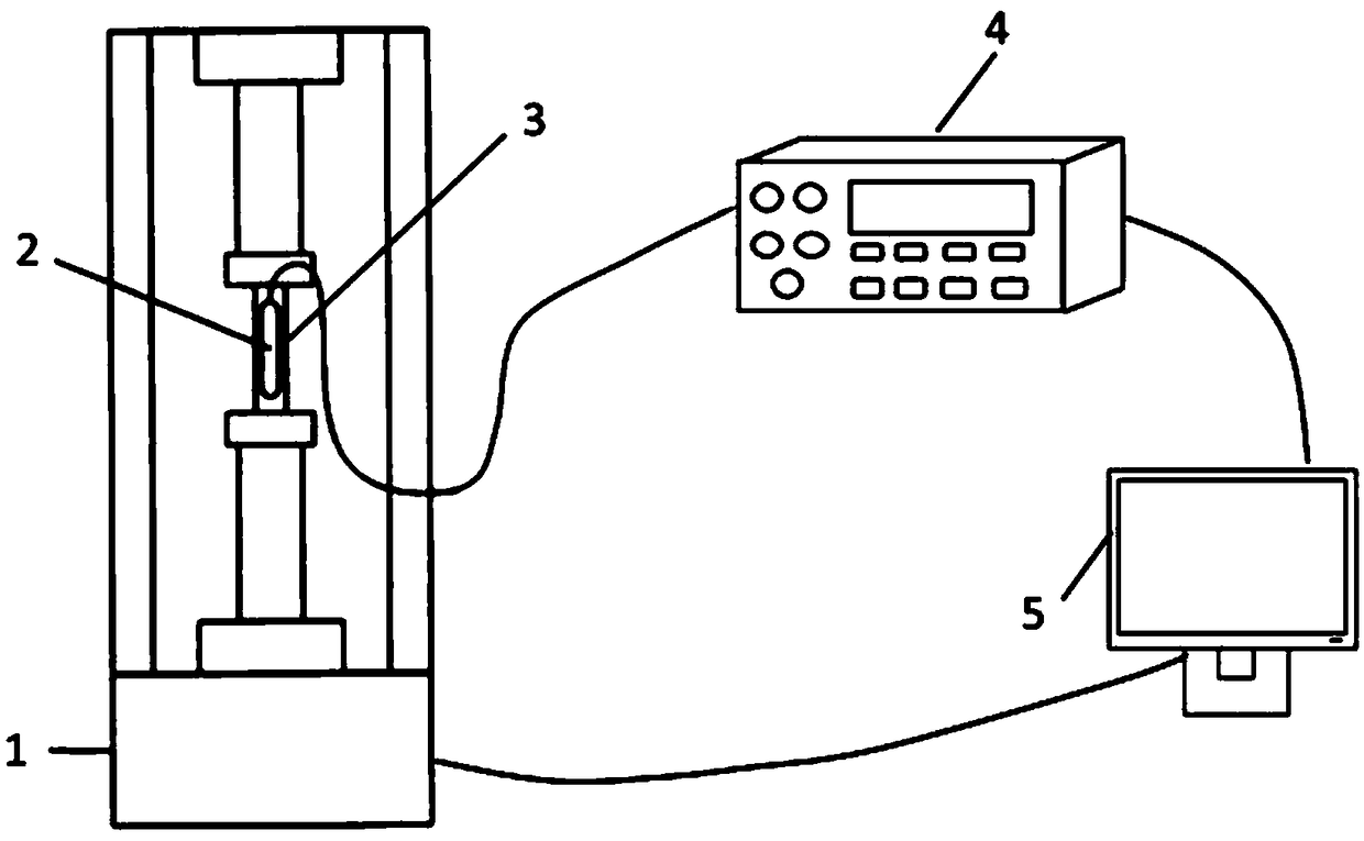
[0029] attached figure 1 Setup diagram of the calibration system for the fiber optic strain sensor. The model of the optical fiber demodulator used in this embodiment is si255-16-ST / 160-NO of MOI Company, its measurement range is -15000—15000με, and the demodulation accuracy is 1pm. The central wavelength of the bare optical fiber used in the embodiment is 1536nm, the central wavelength of the optical fiber strain sensor to be calibrated is 1588nm, and its measuring range is 0-2000με with a resolution of 0.5με.

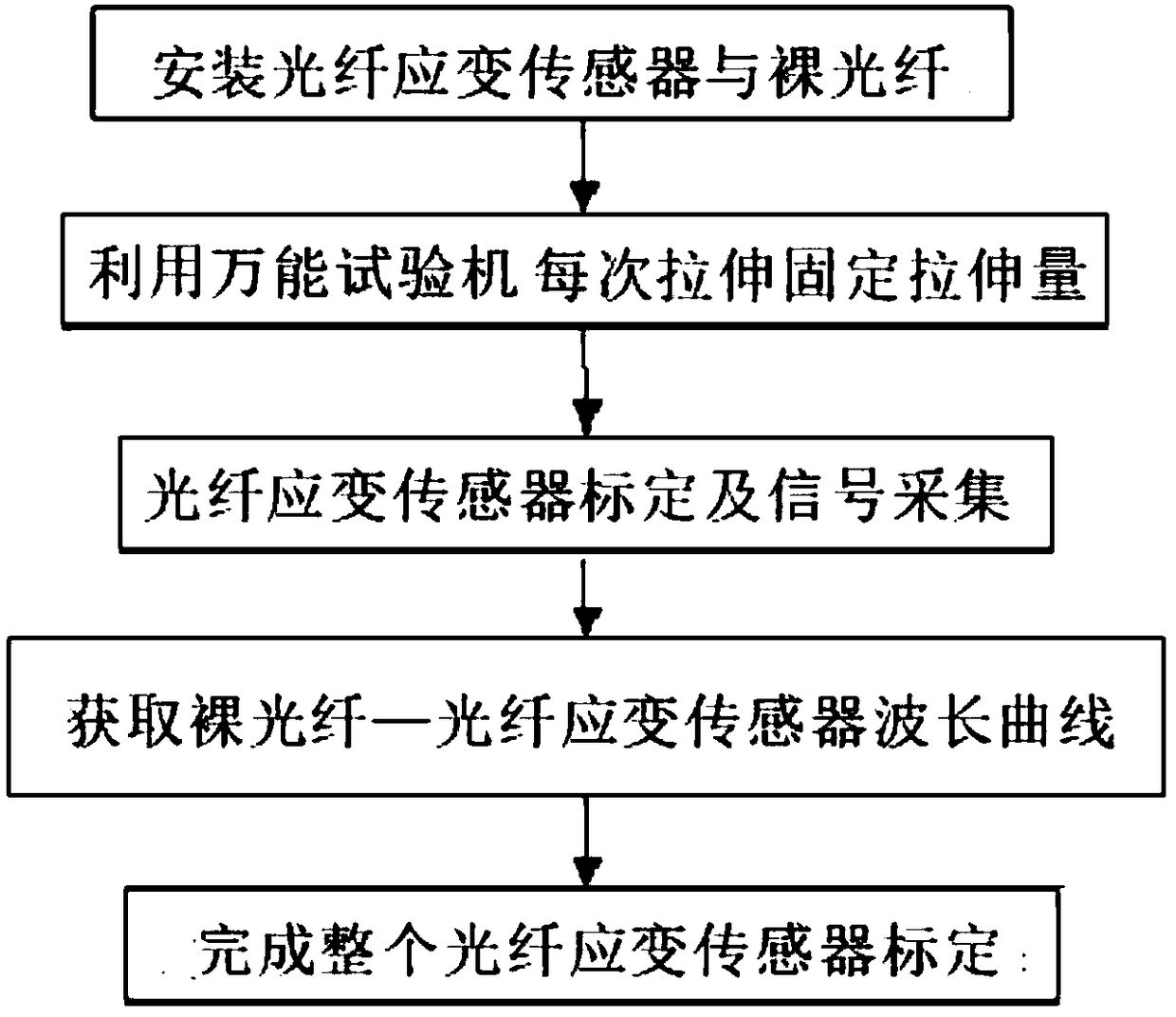
[0030] attached figure 2 It is a flow chart of the optical fiber strain sensor calibration method. The entire calibration method is divided into the following three parts, the installation and layout of the optical fiber strain sensor calibration hardware system, the optical fiber strain sensor calibrati...


PUM


Abstract

The invention discloses an optical fiber sensor strain sensitivity calibration method based on a bare optical fiber, belongs to the technical field of detection, and relates to the optical fiber strain sensor sensitivity calibration method based on the bare optical fiber. According to the method, an universal testing machine is used as an intermediary, when same force is loaded on a same specimen,same stress-strain is obtained, and the un-packaged bare optical fiber is used as a reference for calibrating a fiber bragg grating stress-strain sensor. In a calibration process, by operating a computer, the force loaded by a loading device every time is controlled, an optical fiber demodulation instrument is controlled to acquire measurement data, calibration data is used for being compared with the bare optical fiber, and the sensitivity of the fiber bragg grating strain sensor is obtained, so that a strain character of the fiber bragg grating sensor is accurately calibrated. The method issuitable for calibrating sensitivity coefficients of any optical fiber strain study sensors, errors caused by the problem of taking conversion from the loaded force to stretching stress, a specimen elasticity modulus range and the like into account are avoided, the calibration precision is greatly improved, moreover, operation is convenient, and the method is fast and easy to popularize.

Description

technical field [0001] The invention belongs to the technical field of detection and relates to a method for calibrating the sensitivity of an optical fiber strain sensor based on a bare optical fiber. Background technique [0002] In the field of measurement technology, fiber grating strain sensors play a very important role. Due to its performance of anti-electromagnetic and atomic radiation interference, mechanical properties of thin diameter, soft quality, and light weight; electrical properties of insulation and non-induction; chemical properties of water resistance, high temperature resistance, corrosion resistance, etc. and high sensitivity, it is compatible with optical fibers. Telemetry technology is inherently compatible and widely used in the field of measurement. The principle is that the light from the light source is sent to the modulator through the optical fiber, and after the parameter to be measured interacts with the light entering the modulation area, th...

Claims


Application Information

Patent Timeline
Patent Type & Authority Applications(China)
IPC IPC(8): G01B11/16
CPCG01B11/165
Inventor 刘巍姜昕彤梁冰冯荻周孟德李肖贾振元马建伟
Owner DALIAN UNIV OF TECH
Why Eureka
Try Eureka