Laser energy supply communication equipment and communication method and power supply method thereof

A communication equipment, laser energy supply technology, applied in the direction of photovoltaic power generation, photovoltaic power station, collector, etc., can solve the problems of reducing electric energy, high power consumption of high-potential nodes, failure of power supply modules, etc., to improve reliability and reduce its own power. The effect of consumption and prolonging life

Pending Publication Date: 2018-11-27
NANJING INST OF TECH
View PDF0 Cites 5 Cited by
  • Summary
  • Abstract
  • Description
  • Claims
  • Application Information

AI Technical Summary

Problems solved by technology

[0004] However, the existing laser energy supply equipment is equipped with a VCSEL laser and a photoelectric detection module between the high-potential node and the low-potential node to realize two-way data communication, but the use of the laser leads to high power consumption of the high-potential node itself, reducing the The power that can be output to peripheral devices affects the energy supply effect
At the same time, the existing laser energy supply equipment still has the problem of poor system reliability, and the power supply module often fails, which seriously affects the reliability and safety of energy supply

Method used


Image

  • Laser energy supply communication equipment and communication method and power supply method thereof
  • Laser energy supply communication equipment and communication method and power supply method thereof
  • Laser energy supply communication equipment and communication method and power supply method thereof

Examples


Embodiment Construction

[0025] The technical solution of the present invention will be described in detail below in conjunction with the accompanying drawings.

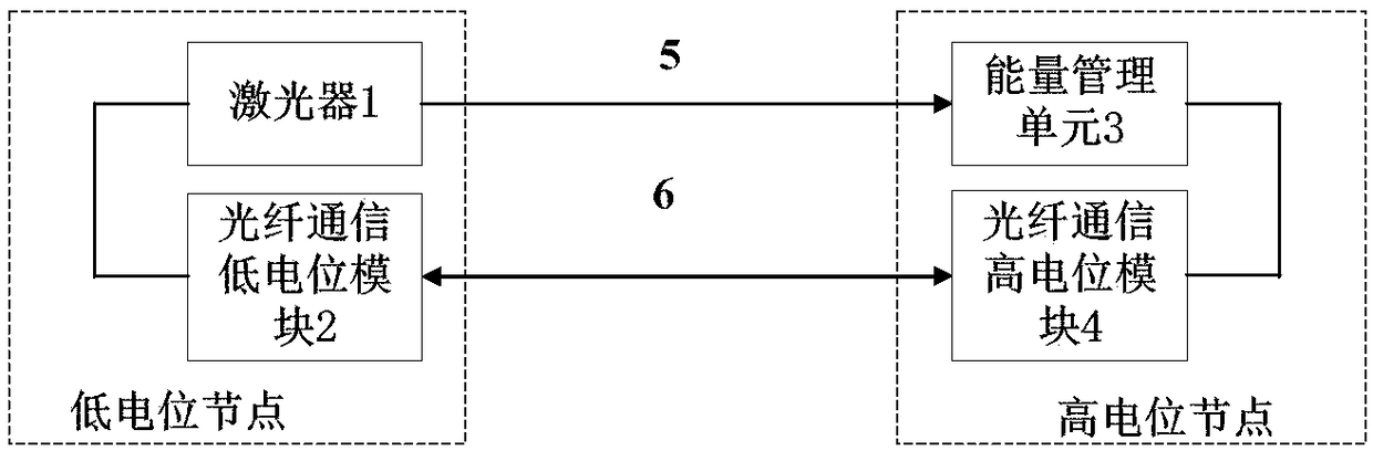
[0026] Such as figure 1 As shown, a laser-powered communication device according to an embodiment of the present invention includes: a laser 1 installed at a low-potential node and an optical fiber communication low-potential module 2, and an energy management unit 3 installed at a high-potential node and a high-potential optical fiber communication module Module 4. The laser 1 is connected to the optical fiber communication low potential module 2, the energy management unit 3 is connected to the optical fiber communication high potential module 4, the laser 1 and the energy management unit 3 are connected through a large core diameter optical fiber 5, the optical fiber communication low potential module 2 is connected to the optical fiber communication high potential The modules 4 are connected by communication fibers 6 .

[0027] In the ...


PUM


Abstract

The invention discloses laser energy supply communication equipment and a communication method and a power supply method thereof. The laser energy supply communication equipment comprises a laser, anoptical fiber communication low potential module, an energy management unit and an optical fiber communication high potential module, wherein the laser and the optical fiber communication low potential module are arranged at the low potential node; the energy management unit and the optical fiber communication high potential module are arranged at a high potential node; the laser is connected withthe optical fiber communication low potential module; the energy management unit and the optical fiber communication high potential module are connected; the laser and the energy management unit areconnected through a big-core-diameter optical fiber; the optical fiber communication low potential module and the optical fiber communication high potential module are connected through a communication optical fiber. The electricity can be effectively supplied to the high-potential monitoring node; the self power consumption of the high potential node can be reduced; the electric energy capable ofbeing used for outputting the peripheral equipment is increased, so that the laser maintains the low-power consumption output state; the service life of the laser is prolonged; the reliability of theenergy supply communication equipment is improved.

Description

technical field [0001] The invention relates to the field of laser-powered communication, in particular to a laser-powered communication device, a communication method, and a power supply method. Background technique [0002] In the context of the rapid construction and development of the Global Energy Internet, the demand for real-time perception of the operating status of the power grid continues to deepen. The development of power system automation and smart grid has made the application of intelligent electronic devices and monitoring sensors in power transmission and transformation equipment more and more extensive. In order to accurately monitor various physical quantities of electrical equipment, a large number of sensor nodes of various types will be densely distributed in the area to be measured. [0003] Using laser transmission in optical fiber to transmit electric energy to remote nodes is an effective way to supply power to high-potential monitoring nodes. It c...

Claims


Application Information

Patent Timeline
Patent Type & Authority Applications(China)
IPC IPC(8): H02S10/00H02S10/10H02J7/35H02J7/00H04B10/80
CPCH02J7/0068H02J7/35H02S10/00H02S10/10H04B10/807Y02E10/50
Inventor 韦朴邓路李辉鲁沈婷
Owner NANJING INST OF TECH
Why Eureka
Try Eureka