Solid-gas microchannel reactor

A microchannel reactor and microchannel technology, applied in chemical/physical/physical chemical reactors, chemical instruments and methods, chemical/physical/physical chemical processes, etc., can solve the problems affecting the contact between gas and microchannel reactor, micro Dirty channel reactors, affecting catalytic efficiency and other issues, to achieve the effect of ensuring contact efficiency, good buffering effect, and improving processing efficiency

Pending Publication Date: 2018-11-30
浙江工业大学上虞研究院有限公司
View PDF0 Cites 3 Cited by
  • Summary
  • Abstract
  • Description
  • Claims
  • Application Information

AI Technical Summary

Problems solved by technology

[0003] In the existing solid-gas microchannel reactor, an inner tube with a catalyst is pierced on a straight sleeve, and then the gas to be reacted is introduced into the sleeve, and the gas will be catalyzed and activated through the inner tube and then flow out from the sleeve. The other end of the tube flows out. During the process of gas catalysis, there may be solid impurities in the gas. If the solid impurities directly enter the microchannel reactor, the solid impurities are

Method used


Image

  • Solid-gas microchannel reactor
  • Solid-gas microchannel reactor
  • Solid-gas microchannel reactor

Examples


Embodiment 1

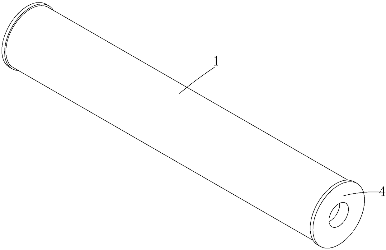
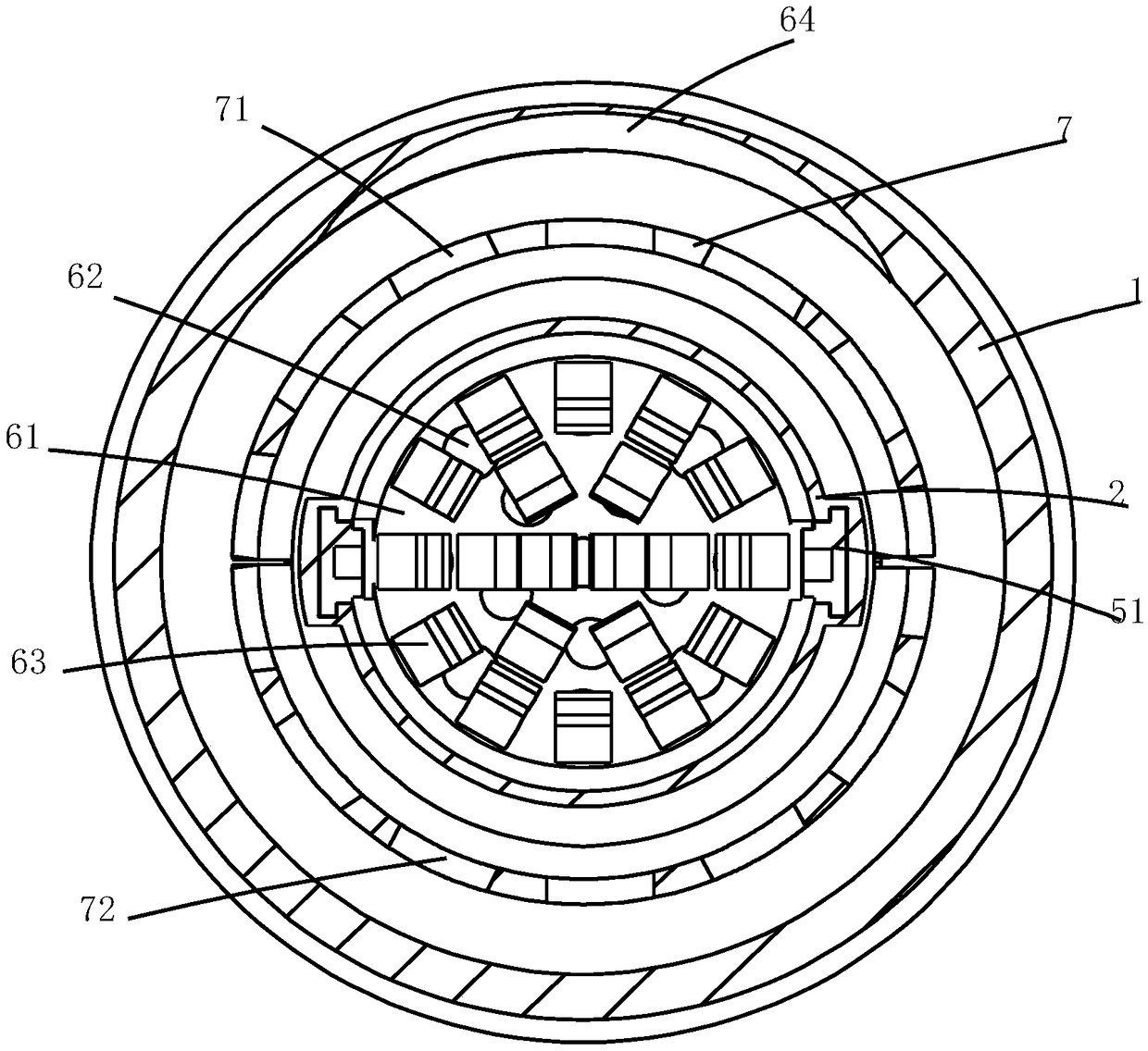
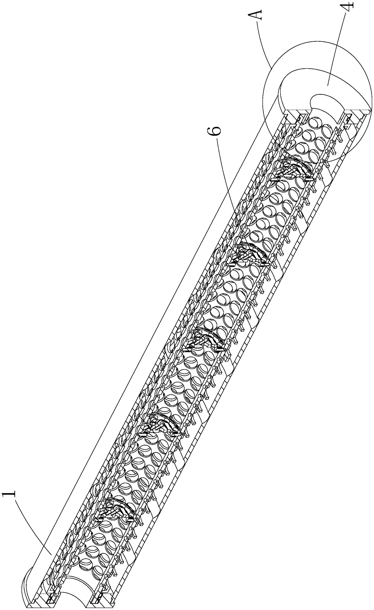
[0043] Such as Figure 1-16Shown, a kind of solid-gas microchannel reactor comprises sleeve pipe 1, reaction tube 2, catalytic structure 3, a plurality of drainage structures 6 and sealing structure 4, wherein said sleeve pipe 1 is a metal tube, and the sleeve pipe The end of 1 is provided with an external thread, and the end of the casing 1 can be connected to reaction microchannels of different specifications and sizes through the thread, and the gas is transported into the casing 1 through the reaction microchannel; the reaction tube 2 is also a metal microchannel. Channel, the reaction tube 2 is provided with a plurality of ventilation openings 20, the ventilation openings 20 can allow the gas entering the reaction tube 2 to flow out through the ventilation openings 20, and then enter the casing 1; and in the reaction The pipe 2 is concave downward except for both ends, and it is formed with a placement recess 24, and the catalytic structure is arranged in the placement re...

Embodiment 2

[0053] Such as Figure 17-20 As shown, the difference between this embodiment and Embodiment 1 is that this embodiment discloses a filter structure 9 for filtering the gas to filter out solid impurities contained in the gas before the gas enters the reaction tube 2, specifically: the Described filter structure 9 comprises air intake pipe 91, filter 92 and air outlet pipe 93, wherein said air intake pipe 91 and air outlet pipe 93 are all a metal microchannel, and one end of said air inlet pipe 91 is connected to the outlet pipe 93. The phase screw connection of air pipe part 93, the other end of air intake pipe part 91 is movably connected with a metal connection nut 910, and the concrete connection mode of its connection nut 910 is prior art; The filter 92 is a metal filter cartridge with dense filter holes, and the filter 92 is detachably connected to the outlet pipe 93 .

[0054] Specifically, a connection platform 931 is provided on the outlet pipe piece 93, and a screw co...


PUM


Abstract

The invention discloses a solid-gas microchannel reactor. The solid-gas microchannel reactor comprises a casing detachably connected with a microchannel for conveying a gas; a reaction tube traversingthrough the casing and provided with a plurality of ventilation openings; a catalysis structure arranged on the reaction tube and comprising a solid phase drug; a plurality of drainage structures forguiding the gas to move from the middle part of the reaction tube towards the catalysis structure, contact with the inner wall of the casing and afresh traverse through the catalysis structure spirally; and a filtering structure cooperating with the casing to filter the gas not entering the reaction tube in order to remove solid impurities contained in the gas. The drainage structures are arranged, so the gas can traverse through the catalysis structure through the drainage structures in order to carry out a catalysis reaction, thereby it is ensured that the whole gas can be effectively catalytically activated, the gas activation energy is improved, the subsequent reaction efficiency is accelerated, the reaction time is shortened, and the gas treatment efficiency is improved.

Description

technical field [0001] The invention belongs to the technical field of chemical production, in particular to a solid-gas microchannel reactor. Background technique [0002] The solid-gas microchannel reactor is a continuous operation reactor with a tubular shape and a large length-to-diameter ratio. Such reactors can be very long, for example, reactor tubes for propylene dimerization can be measured in kilometers. The structure of the reactor can be a single tube or a multi-tube parallel connection; it can be an empty tube, such as a tube cracking furnace, or a filled tube filled with granular catalysts in the tube for heterogeneous catalytic reactions, such as a column tube Fixed-bed reactor; solid-gas microchannel reactor is suitable for both liquid phase reaction and gas phase reaction. [0003] In the existing solid-gas microchannel reactor, an inner tube with a catalyst is pierced on a straight sleeve, and then the gas to be reacted is passed into the sleeve, and the ...

Claims


Application Information

Patent Timeline
IPC IPC(8): B01J19/00
CPCB01J19/0093B01J2219/00792B01J2219/00909B01J2219/0099
Inventor 贾建洪
Owner 浙江工业大学上虞研究院有限公司
Why Eureka
Try Eureka