
Multifunctional machine tool limiting device

A multi-functional machine tool and limit device technology, applied in feeding devices, metal processing machinery parts, metal processing, etc., can solve problems such as difficult stop, easy drop of contacts, machine tool impact, etc., to prevent mechanical collisions and improve reliability Effects on sex and safety

Pending Publication Date: 2018-11-30
SHAANXI SCI TECH UNIV
View PDF0 Cites 2 Cited by
  • Summary
  • Abstract
  • Description
  • Claims
  • Application Information

AI Technical Summary

Problems solved by technology

Due to the large mass of the moving unit of the gantry machine tool itself, the kinetic energy is large during the movement, and it is not easy to stop. The servo system may run away, causing the gantry beam as the moving unit to fall rapidly when moving along the bed, and cause damage to the machine tool. Strong impact can easily cause damage to the machine tool or the gantry beam as the mobile unit
[0003] At present, some domestic machine tool moving units use limit blocks to restrict the position of the guide rail, and use direct collision between machines to control the feed displacement of the machine tool, but this method is noisy and causes great damage to the machine tool
There are also some machine tools that use travel switches to control the feed displacement of the machine tool. However, due to the relatively simple structural design, troublesome adjustment, easy drop of contacts, single function, poor reliability, and easy damage to the limit block, it is still a problem. Can not meet the requirements of modern factories

Method used


Image

  • Multifunctional machine tool limiting device
  • Multifunctional machine tool limiting device
  • Multifunctional machine tool limiting device

Examples


Embodiment Construction

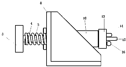
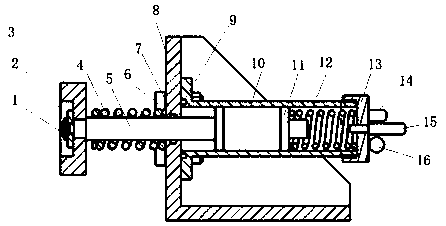
[0013] A limit device for a multifunctional machine tool, comprising a hydraulic buffer mechanism and a detection and feedback element. The base L plate 8 is fixedly installed on the machine tool, the hydraulic buffer mechanism is fixedly installed on the base L plate 8 , and the detection feedback element is installed on the end face 13 of the hydraulic buffer mechanism.

[0014] The hydraulic buffer mechanism is used to block the movement displacement of the machine tool moving unit, including screw 1, pressure plate 2, baffle plate 3, external compression spring 4, external piston rod 5, bolt 6, horizontal sealing ring 7, base L plate 8, vertical sealing Ring 9, flange 10, inner piston 11, inner compression spring 12, end cap 13. The end plate 3 is fixedly connected with the outer piston rod 5 through the screw 1, the outer compression spring 4 is set on the outer piston rod 5, one end of the flange 10 is fixedly connected with the base L plate 8 through the bolt 6, and the...


PUM


Abstract

The invention discloses a multifunctional large-scale guide rail limiting device. The limiting device comprises a hydraulic buffering mechanism used for stopping rapid movement of a machine tool moving unit, a mechanical base used for allowing the hydraulic buffering mechanism to be installed and indirectly bearing the impact force of the machine tool moving unit, and detection feedback components, wherein the mechanical base is installed on a machine tool, and the hydraulic buffering mechanism is fixedly installed on the mechanical base. According to the multifunctional large-scale guide raillimiting device, when the machine tool moving unit moves quickly and impacts the hydraulic buffering mechanism, direct mechanical collision is effectively prevented, so that a certain safety protection effect is achieved; a pressure sensor is used for conducting real-time feedback detection, when a detection signal reaches a warning value, the machine tool can make a timely action command; and the limiting device solves the problems that an existing machine tool limiting device is poor in reliability, short in service life and the like, and has a certain application prospect.

Description

technical field [0001] The invention belongs to the technical field of mechanical design, and relates to a limit device of a multifunctional machine tool. Background technique [0002] With the rapid development of my country's machinery industry, more and more industries have realized mechanization and automation, and various processing machine tools are widely used in the processing of various products, among which, the gantry structure machine tool is the most widely used. During the machining process, the gantry beam of the gantry machine tool, as the fast moving unit of the whole machine tool, moves back and forth quickly along the bed above the machine tool under the drive of the machine servo system to realize the processing of parts. Due to the large mass of the moving unit of the gantry machine tool itself, the kinetic energy is large during the movement, and it is not easy to stop. The servo system may run away, causing the gantry beam as the moving unit to fall ra...

Claims


Application Information

Patent Timeline
IPC IPC(8): B23Q5/52B23Q5/58
CPCB23Q5/52B23Q5/58
Inventor 赵永强崔鑫侯红玲
Owner SHAANXI SCI TECH UNIV
Learn More