Multichannel microfluidic optical detection system

An optical detection and microfluidic technology, which is applied in the field of fluorescence detection, can solve the problems of high system structure accuracy, affecting the accuracy of detection results, and high light source power, so as to shorten the detection time, reduce power and meet the detection requirements.

Active Publication Date: 2018-11-30
苏州索真生物技术有限公司 +1
View PDF8 Cites 2 Cited by
  • Summary
  • Abstract
  • Description
  • Claims
  • Application Information

AI Technical Summary

Problems solved by technology

However, the change of light intensity is easily affected by the environment. Once there is interference in the optical path, it will seriously affect the accuracy of the detection results.
In addition, fluorescence detection mostly directly irradiates the laser on the micro-droplets, and the laser light sour

Method used


Image

  • Multichannel microfluidic optical detection system
  • Multichannel microfluidic optical detection system
  • Multichannel microfluidic optical detection system

Examples


Embodiment 1

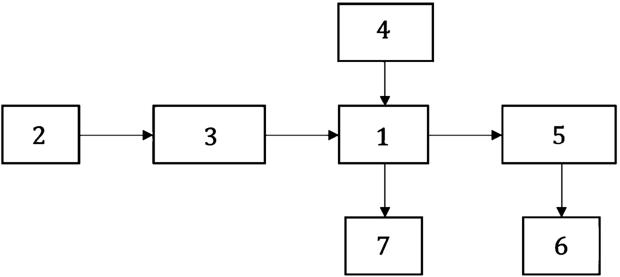
[0032] Such as figure 1 As shown, this embodiment includes:

[0033] The light source 2 is used to output optical signals; a laser light source is used, and the number is one;

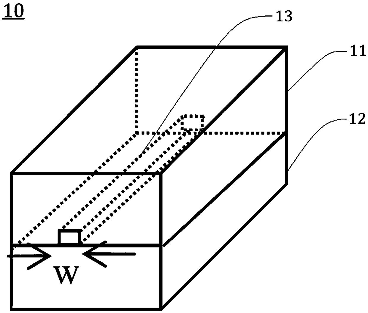
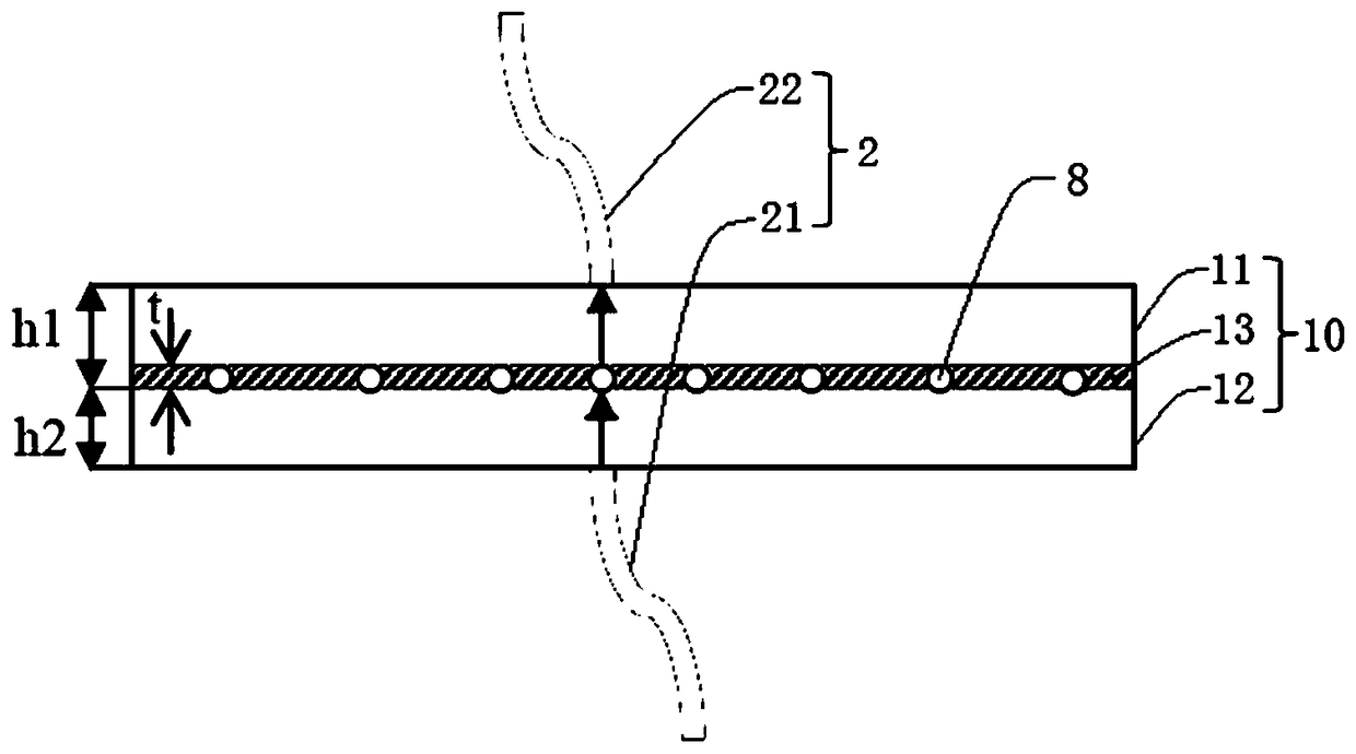
[0034] The multi-channel microfluidic module 1 is formed by arranging two single-channel microfluidic chips 10 side by side; the structure of a single single-channel microfluidic chip 10 is as follows: figure 2 shown;

[0035] A light source coupling control module 3, configured to distribute input optical signals to each microchannel;

[0036] The liquid circuit control module 4 is used to control the generation frequency and flow rate of microdroplets in each microchannel 13;

[0037] The photoelectric conversion module 5 is used to receive the optical signal through the microchannel 13 to regenerate and amplify the electrical signal; the number is one;


PUM


Abstract

The invention provides a multichannel microfluidic optical detection system in the technical field of fluorescence detection. The multichannel microfluidic optical detection system comprises a light source, a multichannel microfluidic module, a light source coupling control module, a liquid path control module, a light-electricity conversion module and a detection analysis module, wherein the light source is used for outputting optical signals, and one light source is available; the multichannel microfluidic module is provided with at least two microchannels; the light source coupling controlmodule is used for inputting the optical signals to each microchannel in a distribution manner; the liquid path control module is used for controlling the generation frequency and flow velocity of microdrops in each microchannel; the light-electricity conversion module is used for receiving the optical signals passing through the microchannels, generating electric signals, and amplifying the electric signals; and the detection analysis module is electrically connected with the light-electricity conversion module for analyzing the amplified electric signals, and thus a detection result is obtained. For the multichannel microfluidic optical detection system provided by the invention, the single light source is adopted for realizing the detection for multiple channels, and meanwhile, the increase of power of the light source due to the increase of the number of the channels is also avoided.

Description

technical field [0001] The invention relates to a technology in the field of fluorescence detection, in particular to a multi-channel microfluidic optical detection system. Background technique [0002] Optical fluorescence detection technology is the most commonly used detection method in DNA detection. Fluorescence detection uses a laser light source. After the photoelectric conversion module receives and detects the change of the optical signal of the micro-droplet after being irradiated by fluorescence, the optical signal is converted into an electrical signal. The detection result is obtained through data collection and algorithm analysis of the electrical signal. [0003] In the prior art, fluorescence detection requires an excitation light source to emit a certain power of irradiation light. After the microdroplets added with fluorescent dyes are irradiated, the DNA in the microdroplets absorbs enough energy to emit detectable fluorescence. However, the change of lig...

Claims


Application Information

Patent Timeline
IPC IPC(8): C12M1/34C12M1/00
CPCC12Q1/6809C12Q2563/159C12Q2563/107
Inventor 陈谦李展刘泓赵峻岭付美文张路
Owner 苏州索真生物技术有限公司
Why Eureka
Try Eureka