Hydraulic power generation device for smart city landscape

A technology for hydroelectric power generation devices and urban landscapes, which is applied in the directions of hydropower generation, drinking water installations, water supply installations, etc., can solve the problems of wasting water resources, affecting the surrounding environment, and increasing the overall energy consumption of the city, so as to avoid unnecessary losses and avoid The enrichment of impurities and the effect of avoiding urban waterlogging

Active Publication Date: 2018-11-30
吴克峰
View PDF12 Cites 9 Cited by
  • Summary
  • Abstract
  • Description
  • Claims
  • Application Information

AI Technical Summary

Problems solved by technology

The setting of the building landscape waterfall will not only make the urban landscape more three-dimensional and economical, but also bring certain positive and positive psychological hints to the personnel working in the building, but the building landscape in the prior art The waterfall only pumps water from the...

Method used


Image

  • Hydraulic power generation device for smart city landscape

Examples


Embodiment 1

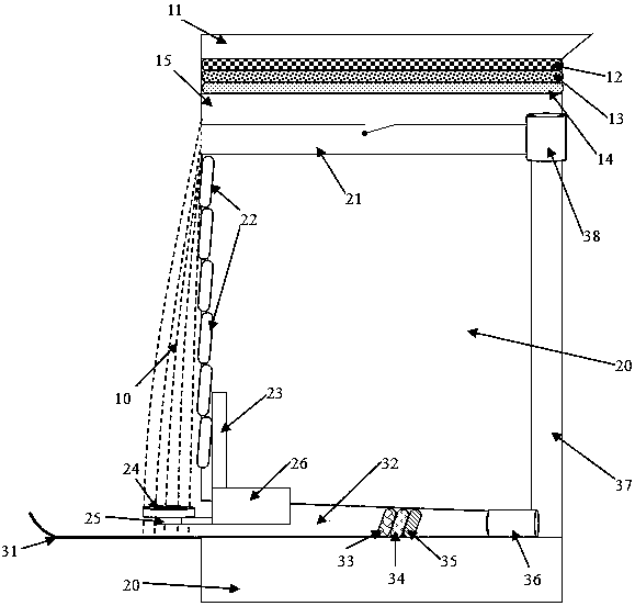
[0026] Such as figure 1 Shown: A smart city landscape hydroelectric power generation device, including rainwater collection and filtration system, energy supply system and circulation system.

[0027] The rainwater collection and filtration system is set on the top of the landscape building, including a rainwater collection trough, a first filter layer, a second filter layer, a third filter layer and a water storage tank; The topmost part of the device is a trough with an opening at the top, which is used to collect rainwater and / or snow falling on landscape buildings, and a first filter layer, a second filter layer and a third filter layer are arranged horizontally on the bottom side of the rain collection trough. filter layer, the first filter layer is a slag particle layer, the second filter layer is a quartz sand particle layer, and the third filter layer is an activated carbon particle layer, in the first filter layer, the second filter layer and the The third filter lay...

Embodiment 2

[0037] A smart city landscape hydroelectric power generation device, including a rainwater collection and filtration system, an energy supply system and a circulation system.

[0038] The rainwater collection and filtration system is set on the top of the landscape building, including a rainwater collection trough, a first filter layer, a second filter layer, a third filter layer and a water storage tank; The topmost part of the device is a trough with an opening at the top, which is used to collect rainwater and / or snow falling on landscape buildings, and a first filter layer, a second filter layer and a third filter layer are arranged horizontally on the bottom side of the rain collection trough. filter layer, the first filter layer is a slag particle layer, the second filter layer is a quartz sand particle layer, and the third filter layer is an activated carbon particle layer, in the first filter layer, the second filter layer and the The third filter layer is separated by...


PUM


Abstract

The invention relates to a hydraulic power generation device for a smart city landscape. The hydraulic power generation device includes a rainwater collection and filtration system, an energy supply system and a circulation system. By arranging a hydraulic turbine at the bottom of a landscape waterfall, the very high kinetic energy of a water body with very high potential energy at the bottom is instantly converted into the kinetic energy of the hydraulic turbine rotation, thus the landscape is realized completely without the splash of the waterfall and impact on an external blocking plate; and through the arrangement of hydropower and solar power generation devices, the external energy supply of the whole device is not required; and the water body used in the landscape uses rainwater supply, the external water body supply is not required basically, and the self- sufficiency of energy and resources is really realized.

Description

technical field [0001] The invention belongs to the field of new energy power generation, and also relates to the field of smart cities, in particular to a landscape water power generation device for smart cities. Background technique [0002] The concept of smart city has increasingly attracted the attention of urban planners and researchers. At present, many buildings are being constructed and used with the concept of smart city. The setting of the building landscape waterfall will not only make the urban landscape more three-dimensional and economical, but also bring certain positive and positive psychological hints to the personnel working in the building, but the building landscape in the prior art The waterfall only draws water from the lower part to the upper part, releases it through a certain outlet, and then recycles the water body. It requires the intervention of external energy, and its water body has a partial impact on the surrounding environment, which not onl...

Claims


Application Information

Patent Timeline
IPC IPC(8): E03B3/02E04D13/00F03B1/00F03B13/00C02F9/08
CPCC02F1/001C02F1/283C02F1/32C02F9/00C02F2103/001C02F2301/046C02F2301/08E03B3/02E04D13/00F03B1/00F03B13/00Y02E10/20Y02A20/108
Inventor 张有明
Owner 吴克峰
Why Eureka
Try Eureka