Sulfur-removing, pressurizing and storing device for single-well casing gas

A technology for storage devices and well casings, which is applied in the direction of gas fuel, wellbore/well components, and production fluids, can solve the problems of high energy consumption, inapplicability, and low efficiency of booster pumps, and achieve energy consumption and structure simple and durable effect

Active Publication Date: 2018-11-30
安徽翰邦科技咨询有限公司
View PDF12 Cites 2 Cited by
  • Summary
  • Abstract
  • Description
  • Claims
  • Application Information

AI Technical Summary

Problems solved by technology

But the problem is that it only uses the power of the pumping unit to perform the exhaust function, and the discharged natural gas is compressed and input into the oil pipeline.
However, the disadvantage of this patent is that it is not suitable for single well operation in the field, because the single well in the field has no gas pipeline installed due to the long distance between the wells, and only by putting the compressed natural gas into the storage tank, Then it will be pulled away by tank truck at regular intervals
But its existing problems are: high energy consumption, multiple booster pumps consume a lot of energy, high cost, and the benefit is not high compared with the value of the collected natural gas

Method used


Image

  • Sulfur-removing, pressurizing and storing device for single-well casing gas
  • Sulfur-removing, pressurizing and storing device for single-well casing gas
  • Sulfur-removing, pressurizing and storing device for single-well casing gas

Examples


Embodiment 1

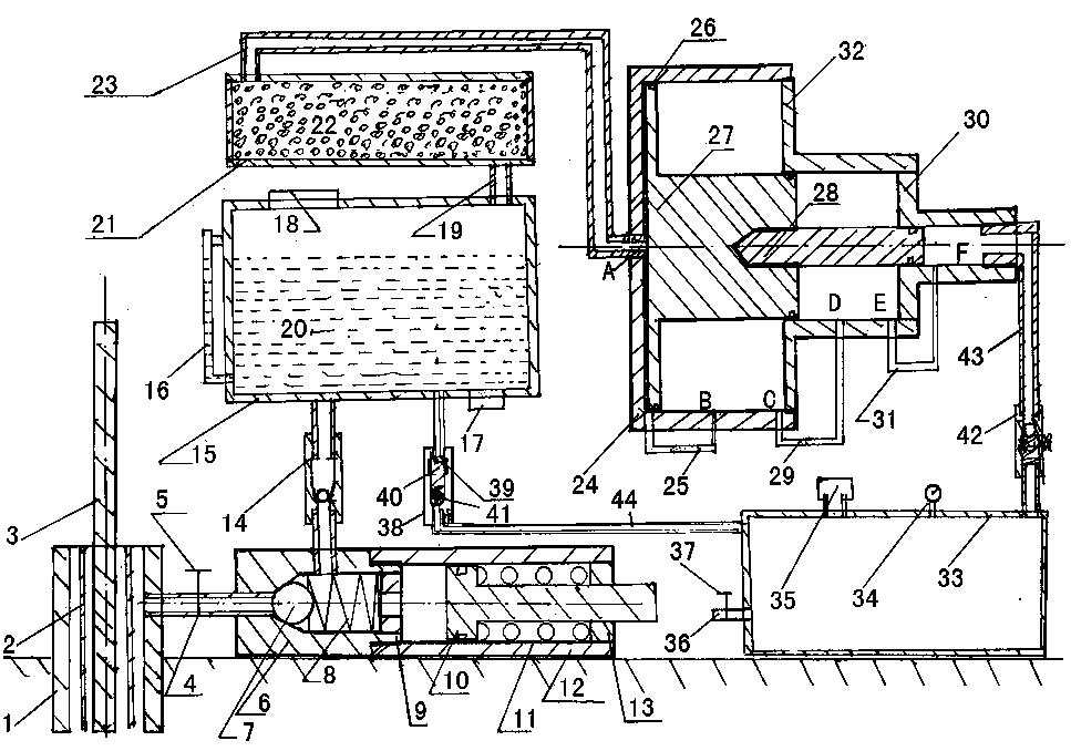
[0034] Embodiment 1, with reference to attached Figure 1-5 , the single well casing gas desulfurization pressurized storage device mentioned in the present invention, its technical solution is: include oil extraction exhaust device, chemical reaction device, natural gas drying device and multi-stage labor-saving gas compression device and compressed gas storage tank 33, The described oil extraction and exhaust device will be connected to the chemical reaction device through the gas outlet pipe after the natural gas between the casing pipe 1 and the oil pipe 2 is produced, and the chemical reaction device includes a reaction tank 15, a liquid level gauge 16, a liquid discharge Hole 17, injection hole 18, gas-collecting connecting pipe 19, chemical reaction liquid 20, the chemical reaction liquid 20 that is housed in the reaction tank 15 adopts sodium hydroxide solution, and one side of the reaction tank 15 is provided with a liquid level gauge 16, the top One side is provided ...

Embodiment 2

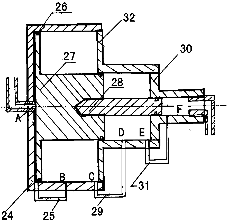
[0052] Embodiment 2, with reference to attached Image 6 The difference between the present invention and Embodiment 1 is: the left end face of the supercharging power cylinder 24 of the multi-stage labor-saving gas compression device is connected to the compression intake pipe 23, and the above-mentioned compression intake pipe 23 is formed by combining a dynamic sealing steel pipe and a PVC steel wire composite pipe , and the left end of the power piston 27 is connected and fixed through the dynamic sealing steel pipe, and the dynamic sealing steel pipe between the power piston 27 and the left end inner wall of the booster power cylinder 24 is provided with a plurality of air outlets, that is, the A place. Moreover, the inner wall of the left end of the power piston 27 and the left end of the supercharging power cylinder 24 is provided with a limiting block 47, and the position of the intake end of the supercharging air supply pipe 25 moves to the right.

[0053] The PVC ste...

Embodiment 3

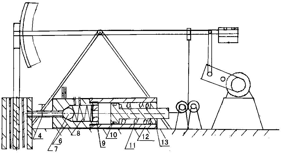
[0058] Embodiment 3, with reference to attached Figure 10 The difference between the technical solution mentioned in the present invention and Embodiment 2 is that one end of the compressed air intake pipe 23 is connected to the gas dryer 21, the other end is connected to the B of the booster power cylinder 24, and the power piston 27 is connected to The left end is connected with the dynamic seal shaft, and the outer end of the dynamic seal shaft is connected by a wire rope, and the wire rope is connected to the rear end of the beam of the beam pumping unit by going around the fixed pulley, so that the beam moves up and down at any time, moving with the wire rope, and then The steel wire rope is driven to move with the dynamic seal shaft, thereby giving the power piston 27 an external force.

[0059] The use method of the present invention differs from Embodiment 1 in that: the pressurization process of the multi-stage labor-saving gas compression device is different, specif...


PUM

PropertyMeasurementUnit
diameteraaaaaaaaaa

Abstract

The invention relates to a sulfur-removing, pressurizing and storing device for single-well casing gas. According to the technical scheme, the sulfur-removing, pressurizing and storing device comprises an oil-extraction exhausting device, a chemical reaction device, a natural gas drying device, a multistage labor-saving gas compression device and a compressed gas storage tank; the oil-extraction exhausting device is used for delivering casing gas into the chemical reaction device through a gas outlet pipe after casing gas is extracted; an inner cavity of a gas dryer is filled with a drying agent, and the gas dryer is provided with a compression gas inlet pipe, and is communicated with a reaction tank through a gas-collection connecting pipe; dried natural gas is compressed into a compression storage tank through the multistage labor-saving gas compression device. The sulfur-removing, pressurizing and storing device has the advantages that through reciprocating motion of a beam-pumpingunit, natural gas in a casing pipe can be exhausted and processed in time, and is compressed through the multistage labor-saving gas compression device, and the compressed gas is stored in the gas storage tank, and then is transported away timely through a tank truck; the sulfur-removing, pressurizing and storing device is simple and durable in structure, great reduction of energy consumption canbe achieved, and as the device adopts a mechanical structure, the device is more durable.

Description

technical field [0001] The invention relates to an oil field single well production auxiliary device and method, in particular to a single well casing gas desulfurization pressurized storage device. Background technique [0002] In oil extraction, there are many field single wells, and there are also a large number of high permeability wells in these single wells. Due to the large amount of natural gas associated in the formation, it is not enough to form natural gas development wells. In this way, in the process of oil extraction, due to a large number of The existence of gas will cause the gas pressure in the casing of the oil well to rise, and the dynamic liquid level of the oil well will drop due to the rise of gas pressure, which will lead to insufficient liquid supply of the oil well. The gas is released or drawn out for combustion. After the gas is released, the dynamic liquid level of the casing will be raised to the normal height, and then the oil production operati...

Claims


Application Information

Patent Timeline
Patent Type & Authority Applications(China)
IPC IPC(8): E21B43/00E21B43/34C10L3/10
CPCC10L3/106E21B43/00E21B43/34
Inventor 马弘毅
Owner 安徽翰邦科技咨询有限公司
Why Eureka
Try Eureka