Food high pressure pump pulsation reduction device
A high-pressure pump and food technology, applied in the direction of pump components, pulse balance, machine/engine, etc., can solve problems such as colony reproduction, hidden dangers of production system safety, and unsatisfactory effect of buffer to eliminate pulsation, so as to absorb fluctuations in flow and pressure , stable flow and reduced impact
- Summary
- Abstract
- Description
- Claims
- Application Information
AI Technical Summary
Problems solved by technology
Method used
Image
Examples
Embodiment 1
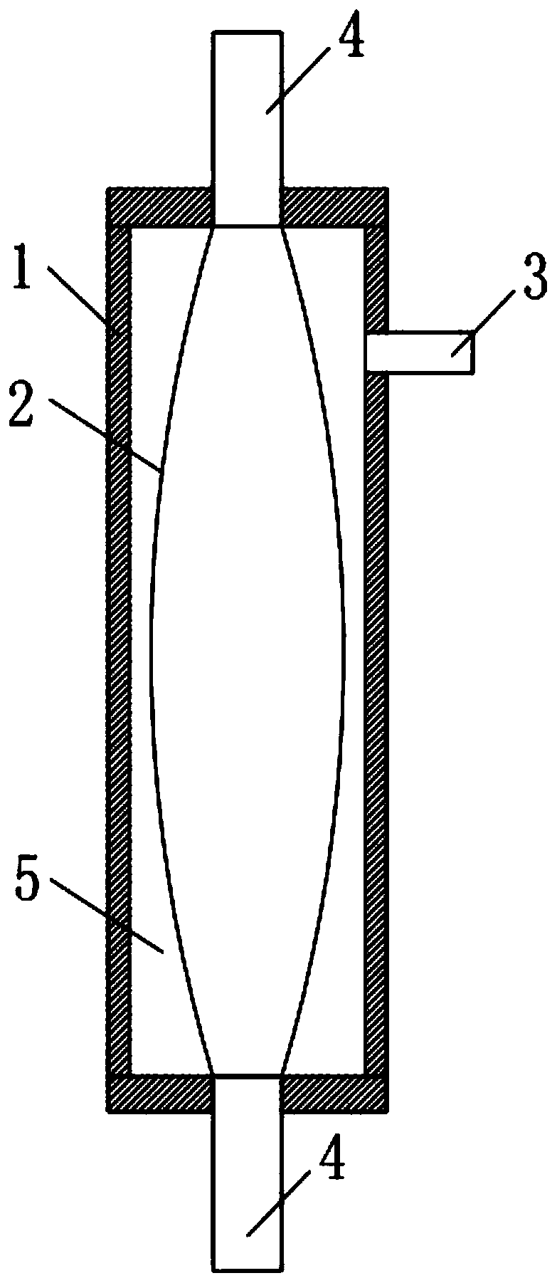
[0032] Such as figure 1 As shown, in this embodiment, the food high-pressure pump pulsation reduction device includes a housing 1 with a housing space, an air bag 2, an inflator 3 and a connecting device 4. The housing 1 is a cylindrical structure, and both ends are provided with There are connecting devices 4, respectively connected to the inlet and outlet of the material of the production system, the airbag 2 is arranged in the housing 1, and its two ends communicate with the connecting devices 4 at the two ends of the housing 1 respectively A closed air chamber 5 is formed between the inner wall of the housing 1 and the air bag 2 , the inflator 3 is arranged on the side wall of the housing 1 , and the air chamber 5 communicates with the inflator 3 .
[0033] In this embodiment, in order to ensure the pressure bearing capacity and service life of the high-pressure pulsation buffer, the aspect ratio of the housing 1 is greater than 5, and the ratio of the outer diameter to th...
Embodiment 2
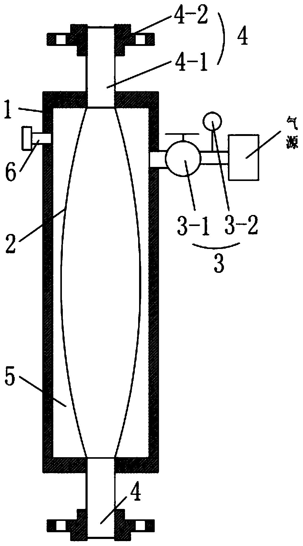
[0037] Such as figure 2 As shown, in this embodiment, the inflation device 3 includes an inflation valve 3-1 and a pressure gauge 3-2, and the inflation valve 3-1 is fixedly arranged on the side wall of the housing 1 and connected to the 5, the other end of the inflation valve 3-1 communicates with the gas source through the inflation tube, and the pressure gauge 3-2 is arranged on the inflation tube.
[0038]In this embodiment, the connection device 4 includes an infusion tube 4-1 and a flange 4-2, one end of the infusion tube 4-1 is fixedly connected to the end of the housing 1 and connected to the airbag 2 communicates internally, and its other end is fixedly connected to the mounting hole provided at the center of the flange 4-2 and passing through the flange 4-2.
[0039] In this embodiment, the housing 1 is further provided with a safety valve 6 connected to the air chamber 5 .
[0040] In this embodiment, the connecting device 4 is connected in a way of flange butt j...
Embodiment 3
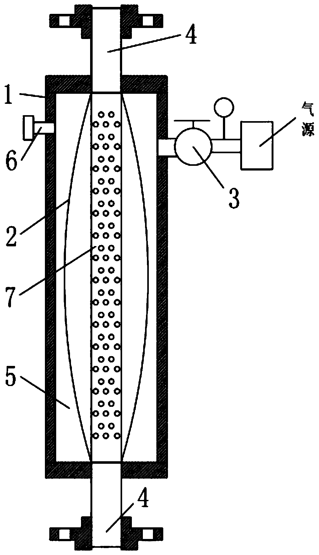
[0045] Such as Figure 3 to Figure 4 As shown, in this embodiment, the airbag 2 is sleeved with a flow stabilizer 7, and the flow stabilizer 7 includes a cylinder body 7-1 with a straight structure, and the two ends of the cylinder body 7-1 are respectively connected to the The infusion tube 4-1 at both ends of the housing 1 is fixedly connected, and the side wall of the cylinder body 7-1 is evenly distributed with a number of through holes penetrating the cylinder wall, and the inner middle position of the cylinder body 7-1 is transversely perpendicular to the cylinder wall. The wall is fixedly provided with a stabilizing plate 7-2, and several through holes are uniformly arranged on the stabilizing plate 7-2.
[0046] In this embodiment, the flow stabilizer 7 is set so that when the airbag 2 expands and contracts, the liquid material needs to pass through the through hole on the cylinder wall of the cylinder 7-1, so as to achieve the effect of slowing down the flow rate, and...
PUM
 Abstract
Description
Claims
Application Information
 - R&D
- Intellectual Property
- Life Sciences
- Materials
- Tech Scout
- Unparalleled Data Quality
- Higher Quality Content
- 60% Fewer Hallucinations
Browse by: Latest US Patents, China's latest patents, Technical Efficacy Thesaurus, Application Domain, Technology Topic, Popular Technical Reports.
© 2025 PatSnap. All rights reserved.Legal|Privacy policy|Modern Slavery Act Transparency Statement|Sitemap|About US| Contact US: help@patsnap.com


